


TopRCModel FW-190
 09-27-2022, 01:22 PM
#1476
the left wing for some reason has the tube and stopper shorter than the right hand side, no choice but to cut about 3/4" off that rear tube.
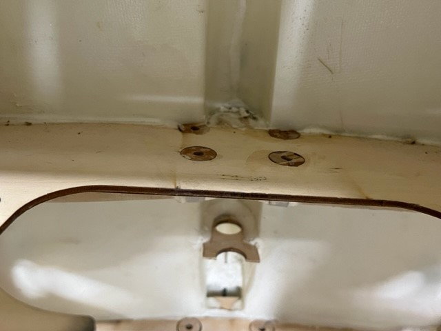
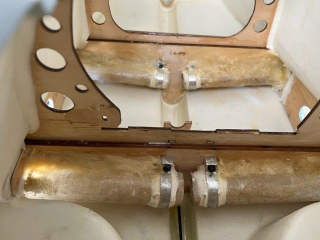
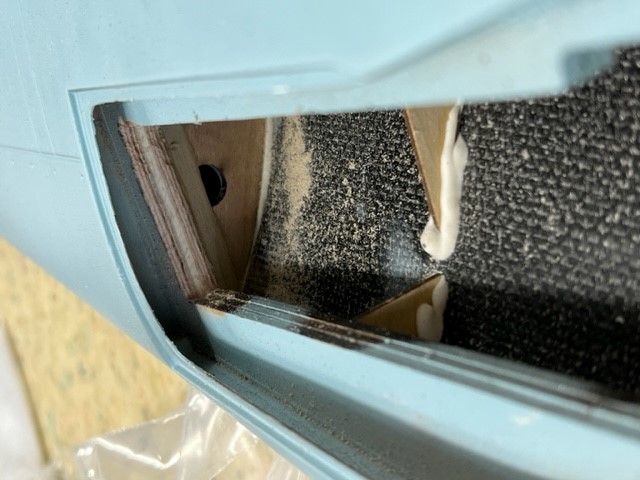
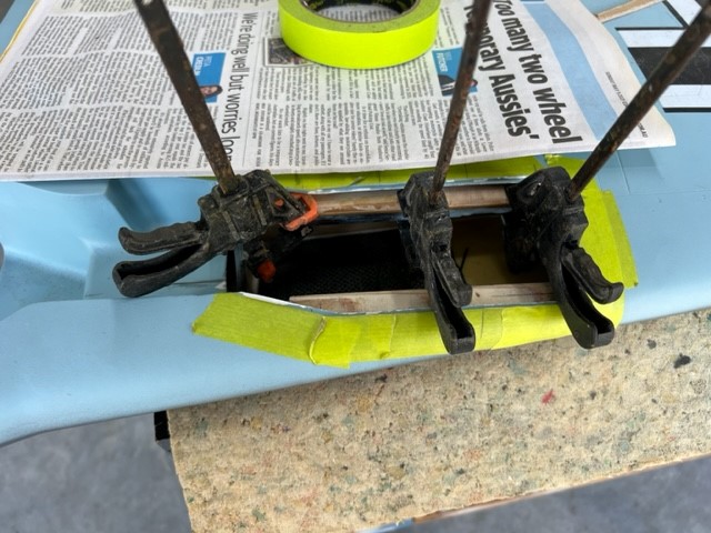
Todays toil so far. The wing tube carry through spars are a known weak point on this model. There have been documented cases of complete structural failure in air with complete loss of the model. Fortunately nobody injured.
I’m adding a 3mm aircraft grade ply doubler to the rear spar and a 6mm one to the front.
Had to remove the tray to gain access but it came out cleanly and will go back I with little trouble.
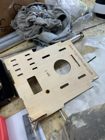
The new ply doubler braces are cut to fit and have been pre-drilled for the bolts. Very happy how that turned out.
Templates from paper and cardboard with use of contour gauge do the trick.
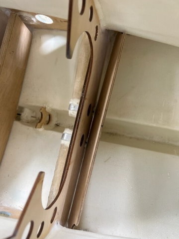
The spars are made of 3 laminations of 3mm chinesum ply. Read c r a p.
The t-nuts only go through two laminations not the rear doubler. This is where the spars are failing.
I’ll be getting longer bolts and there will go through the lot.
Ply braces will glued with hysol. Probably need to get some more ??
Still thinking about carbon fibre on the ply face and may yet do that.
Have to get some 5mm & 3mm aluminium plate for each side of the mounting plate.
That is enough for one day my back and legs are sore.

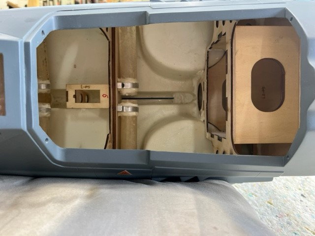

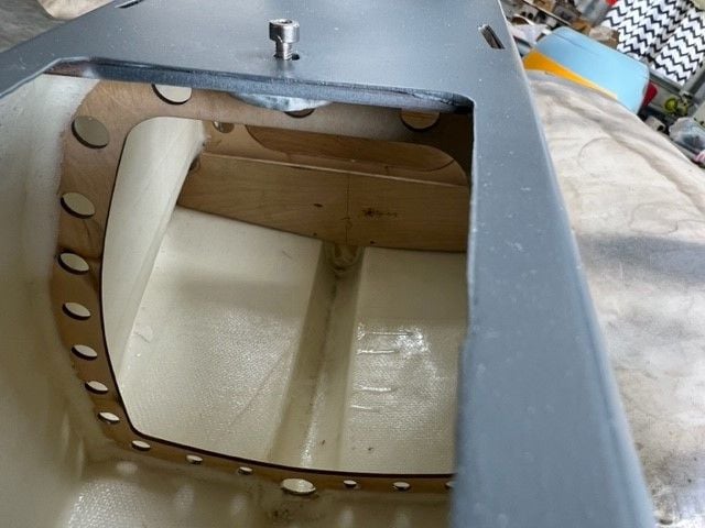
Todays toil so far. The wing tube carry through spars are a known weak point on this model. There have been documented cases of complete structural failure in air with complete loss of the model. Fortunately nobody injured.
I’m adding a 3mm aircraft grade ply doubler to the rear spar and a 6mm one to the front.
Had to remove the tray to gain access but it came out cleanly and will go back I with little trouble.
The new ply doubler braces are cut to fit and have been pre-drilled for the bolts. Very happy how that turned out.
Templates from paper and cardboard with use of contour gauge do the trick.
The spars are made of 3 laminations of 3mm chinesum ply. Read c r a p.
The t-nuts only go through two laminations not the rear doubler. This is where the spars are failing.
I’ll be getting longer bolts and there will go through the lot.
Ply braces will glued with hysol. Probably need to get some more ??
Still thinking about carbon fibre on the ply face and may yet do that.
Have to get some 5mm & 3mm aluminium plate for each side of the mounting plate.
That is enough for one day my back and legs are sore.
 09-27-2022, 01:24 PM
#1477
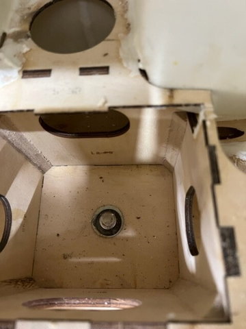
Fabricated some disks out of 3mm ply, spot glued 8 small squares, drew a circle on top one and used the scroll saw to good effect. Bit of sanding down to size.
These go into the circular cut out in the rear wing tube spar former to prevent crushing and reinstate a bit of strength in that area where the bolts go through.
Next will be the 3mm rear and 6mm front ply reinforcing braces which will be epoxied in place. I'll then use slow set hysol around the edges and to tie it into the fuz sides and bottom.
Fuz is bolted to the bench through the firewall which makes it easy to work on for this job.
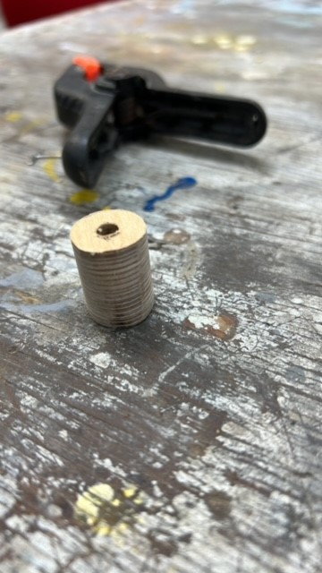
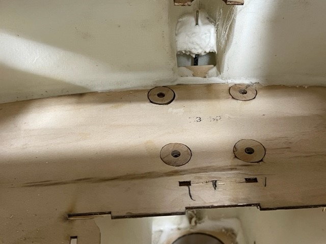
09-27-2022, 01:26 PM
#1478
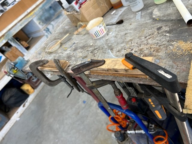
Plywood braces are in, very fiddly getting bolts back in and done up but got it done. 30 min epoxy under the plywood brace and Hyson 9642 around the edges to lock it in to the fuz walls.
Will leav4e it overnight to cure with the wings on.
I bought expensive wing bolts with special nuts from DA Australia and thought I needed the metric M6 bolt but turns out its 1/4-20 bugger.
Thinking I might be better off with a hex head bolt and and right angle drive electric gadget as once the cockpit is in can't see how may hand would fit in there to do it up.
09-27-2022, 01:28 PM
#1479
Mixed up a slurry of resin, chopped up coarse 6 oz cloth and milled fiberglass powder and made a fillet along the top of the wing tubes to provide a bit more support.
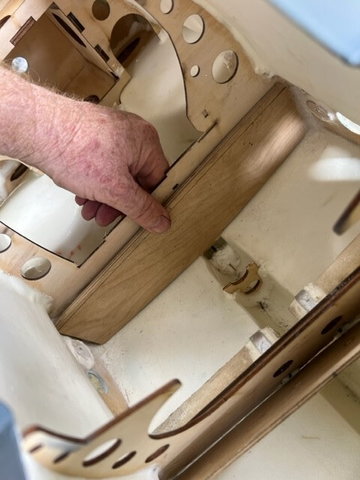
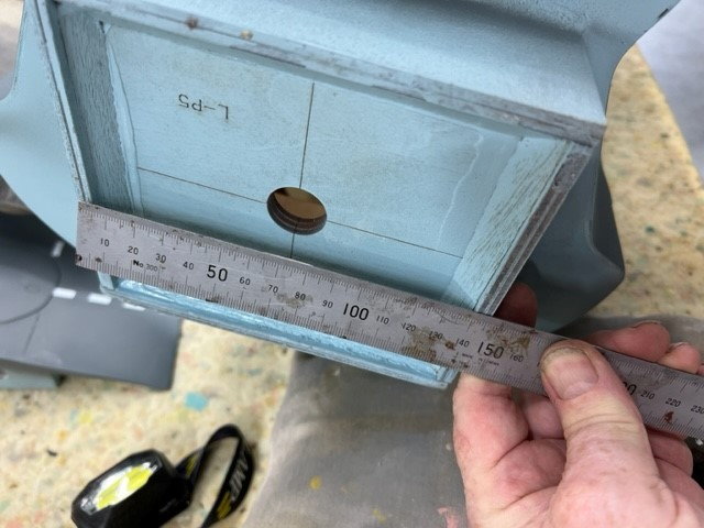
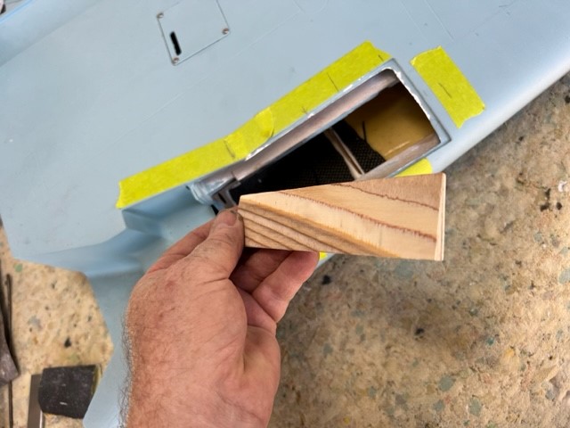
Next job is the tail wheel retract and from what I have read and my initial mockup says the old former bottom half has to come out and a new one about 3/4" forward installed.
Will be lots of measure, try and measure some more before I commit to anything. Will be doing this hopefully without cutting the bottom open.
Stay tuned.
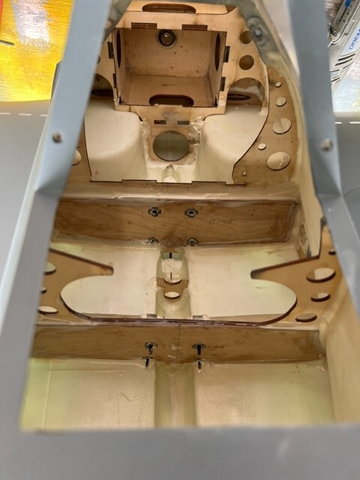
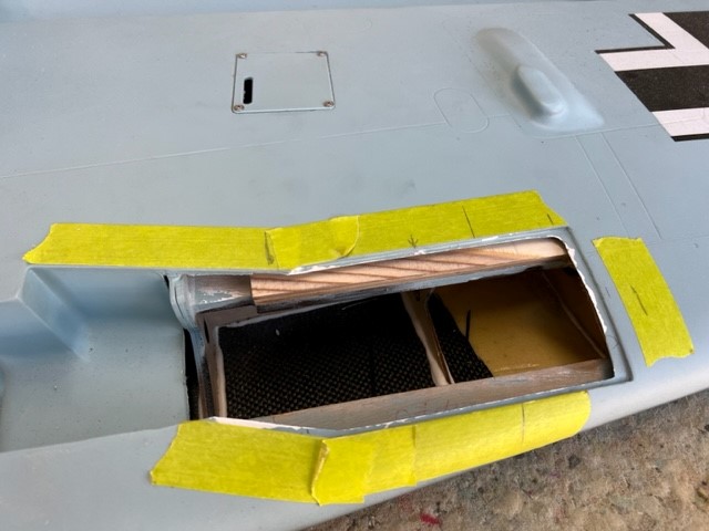
New rear tail retract former made and test fitted, I'm very pleased with the fit. Will take a few more measurements and when satisfied I have it correct I will do a line around the edge with a pencil.
Next will be to triple check where the retract itself needs to be positioned then will make a bottom alignment mark.,
Remove the former, drill and put T-nuts in place etc.
Need to make the former the air cylinder will attach to and then measure, check etc before committing glue to it. I'll probably wick medium CA for that as I can run it down the edges. I will do a fillet of hysol near where the cylinder attaches.
I'll be comping the idea of another to make the top pivot pin a bolt that screws into a piece of hardwood to ensure I can remove the cylinder for servicing.
That will do for today as I want to check a few things and think about it all before I do near it with glue.
As you can see the bottom does not need to be cut out to do the job.


Next job is the tail wheel retract and from what I have read and my initial mockup says the old former bottom half has to come out and a new one about 3/4" forward installed.
Will be lots of measure, try and measure some more before I commit to anything. Will be doing this hopefully without cutting the bottom open.
Stay tuned.
New rear tail retract former made and test fitted, I'm very pleased with the fit. Will take a few more measurements and when satisfied I have it correct I will do a line around the edge with a pencil.
Next will be to triple check where the retract itself needs to be positioned then will make a bottom alignment mark.,
Remove the former, drill and put T-nuts in place etc.
Need to make the former the air cylinder will attach to and then measure, check etc before committing glue to it. I'll probably wick medium CA for that as I can run it down the edges. I will do a fillet of hysol near where the cylinder attaches.
I'll be comping the idea of another to make the top pivot pin a bolt that screws into a piece of hardwood to ensure I can remove the cylinder for servicing.
That will do for today as I want to check a few things and think about it all before I do near it with glue.
As you can see the bottom does not need to be cut out to do the job.
11-06-2022, 06:45 AM
#1483

My Feedback: (2)
I also have a TRC Zero with Saito 90. Use the Dubro 24oz. The engine when properly tuned sips gas. 10 min flight uses just a few ounces of gas. 24 oz tank is plenty, 32 oz is overkill.
I also have the TRC FW190 with DLE 111 here one needs the 32 oz tank.
hope that helps.
I also have the TRC FW190 with DLE 111 here one needs the 32 oz tank.
hope that helps.
11-06-2022, 01:18 PM
#1485
thanks John, I did think 24oz would suffice. 10 min flight time is more than enough with a warbird.
I've read all the threads on several of these failing in the wing tube area. Failure of the plywood due to bolts not going through both formers. They fail right in the V.
I've done mods which should cure that without going over the top like on some of the German forums.
cheers
me
I've read all the threads on several of these failing in the wing tube area. Failure of the plywood due to bolts not going through both formers. They fail right in the V.
I've done mods which should cure that without going over the top like on some of the German forums.
cheers
me
 11-07-2022, 12:41 PM
#1487
11-08-2022, 03:22 PM
#1489
I do that on my H9 1/4 Tiger moth, I have flown it for 45 mins usually passing the controls to a few others. That thing will stooge around happily on 1/4 throttle and still land with a 1/4 tank of fuel left after 45 mins.
MVVS 30 petrol engine.
MVVS 30 petrol engine.
11-13-2022, 12:07 AM
#1490
Gents,
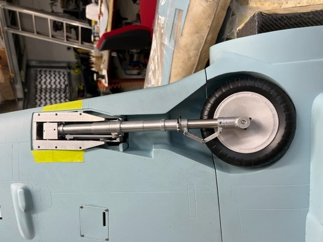
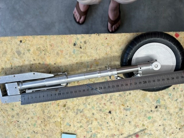
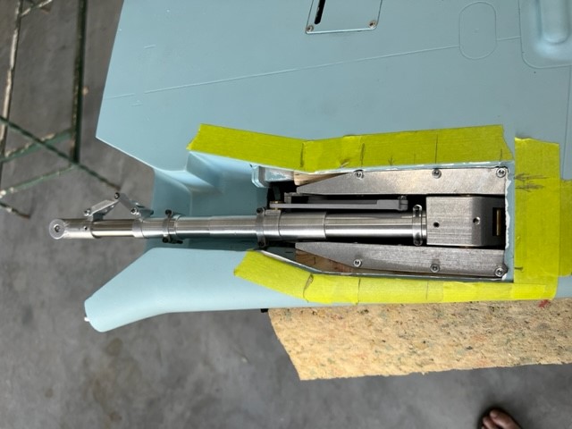
hope somebody can advise on this. Did a trial fit of the main undercarriage and thinking I have the wrong set for this model. Leg appears to be far too long.
Measured the length at 330mm, can anyone advise what length their Sierra legs are, what width the side rails are and did you get the 1/4 scale ones? 6 inch wheels?
See pics below.
thanks
cheers
me
Last edited by planenutzz; 11-13-2022 at 04:10 PM.
11-15-2022, 12:55 PM
#1491
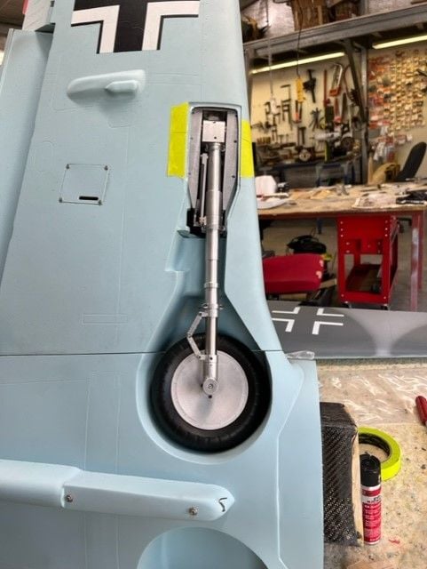
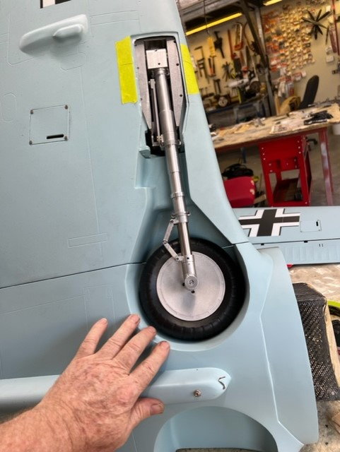
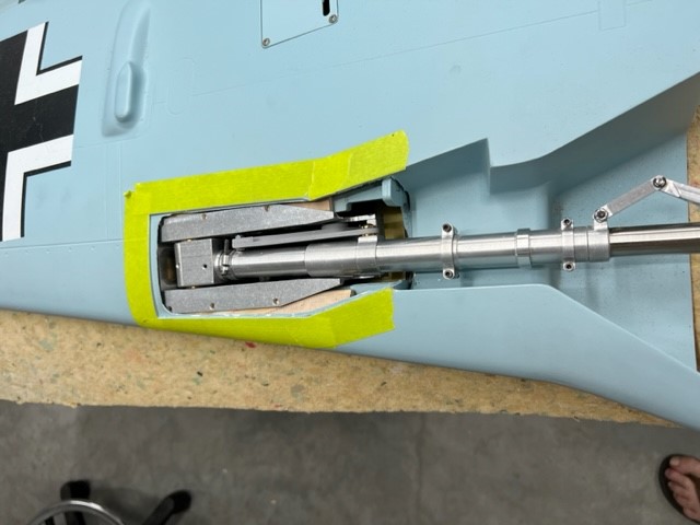
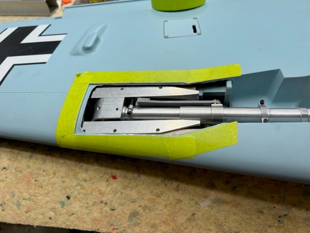
As for the FW190 I managed to get the retract to go in, had to trip those little tap things on edge of the wing skin where they extend into the gear bay and sand that area down a little.
The retract and wheel could then be fitted in though I will need to take out about 5mm at the end of the land gear plywood rail so the retract can be slid out towards the wingtip a little more. I should then have reasonable clearance around the wheel and based on my trial I won't have excessive, or any tow in.
I'ts all doable though I still think the legs are about 15mm too long for this model.
fits but needs to go towards wingtip about 5mm
Happy snaps!

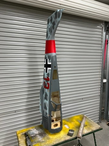
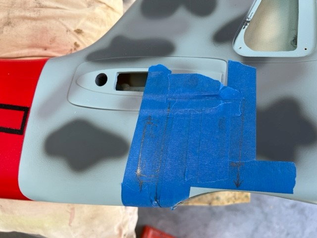
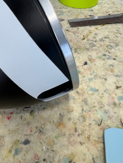
I need to open the blade opening on the spinner. It appears to be a machined or even cast aluminium, quite thick in the wall section of say 3mm. Not sure how to tackle it so I don't wreck it. My thoughts are to tape around the outside to protect and mark where I need the opening to be then slowly and carefully use a dremel grinding stone.
Open to suggestions on how to do it

The retract and wheel could then be fitted in though I will need to take out about 5mm at the end of the land gear plywood rail so the retract can be slid out towards the wingtip a little more. I should then have reasonable clearance around the wheel and based on my trial I won't have excessive, or any tow in.
I'ts all doable though I still think the legs are about 15mm too long for this model.
fits but needs to go towards wingtip about 5mm
Happy snaps!
I need to open the blade opening on the spinner. It appears to be a machined or even cast aluminium, quite thick in the wall section of say 3mm. Not sure how to tackle it so I don't wreck it. My thoughts are to tape around the outside to protect and mark where I need the opening to be then slowly and carefully use a dremel grinding stone.
Open to suggestions on how to do it
The following 2 users liked this post by elmshoot:
apereira (11-19-2022),
planenutzz (11-16-2022)
11-16-2022, 01:26 PM
#1494
Got into the wing and have removed about 8mm from the end of the landing gear mount up near the rib. It has a 10mm triangular gusset under and I am just proud of that so still plenty of meat left there.
I'm confident now I can position the gear exactly where it needs to be. I have half done the other half but battery ran flat flat on the dremel.
I'm confident now I can position the gear exactly where it needs to be. I have half done the other half but battery ran flat flat on the dremel.
11-17-2022, 02:03 PM
#1495
Took out the 8mm on the other wing half and filed about 1mm each side of the Sierra retract mounting plates so they will fit in a lot easier.
Next job is the plywood shims to lift the retract higher in the mount and have the leg parallel to the surface though just under to allow room for the doors.
Next job is the plywood shims to lift the retract higher in the mount and have the leg parallel to the surface though just under to allow room for the doors.
11-19-2022, 01:46 PM
#1496
Long day in the shed working on the gear rail shims. For something that sounds simply there are bloody fiddling and very time consuming.
I got what I thought was one set done but having the top of the gear mount sit just under the lip only to then realise the retract needs to sit a fair bit lower to cater for the gear door.
I am thinking of fitting the door so I can tell when the rails are at correct height but might be easier to just sand a bit off and try it till it is correct. Very time consuming.
Will spend most of today fiddling with it as it is far too windy to go for a fly.
11-20-2022, 12:48 PM
#1497
Well I had a good weekend on the 190, one gear is in and quite happy with how it fits.
Second one I have the shims done and trial fit indicates it good to go however as I am a bit tired after 8 hrs in the shed I will double check tomorrow before committing to epoxy.
I need to get another pair of the gear mounts from Darrell. Will email him later about that.
Have to get some longer 2-56 bolts for the gear brackets and open up the gear doors so that can be reinforced with plywood.
I'll then split the door approx where the full size is split and make a bevel so it will slide over each other.
All fiddly & time consuming jobs.
Happy snaps to prove I wasn't bludging.
First set of shim laminations.
Trial, trim, trial, trim, etc etc etc slowly, slowly catchee monkee
Getting very close
First shim epoxied in place.
And one side is in!!
Second one is about there, double check tomorrow before I epoxy the shims in place. I fit the wing to the fuz, fit the wheel and get final alignments for the leg and how far into the wing the retract needs to go.
Same same, different view.
11-21-2022, 03:28 AM
#1498

Have other people suffered form structural problems? I am buiding mine now, and as always reinforcing what I think is necessary, but I have also read posts/stories of people complaining at a certain gear of airframe or motor just to find
the users do not have the required skills to handle such item, I mean landings, tuning, flying etc.
Would really like to know about experience from other users, Thanks!
Alejandro
the users do not have the required skills to handle such item, I mean landings, tuning, flying etc.
Would really like to know about experience from other users, Thanks!
Alejandro
11-21-2022, 03:30 AM
#1499
I haven't started installing the gear yet (Sierra) what is the reason for the shims? Seen several people using them, is it the gear stance on the ground? or the wheel touching the inner side of the skin?
Thanks
Thanks
11-21-2022, 06:13 AM
#1500
My Feedback: (6)
The ARF as delivered is not designed for the Sierra Retracts. One must do a certain amount of shimming on the gear to get a proper fit particularly if you are going to include the landing gear doors.
There is a scale focused website. RCSB.com where you will find a wealth of information about this plane and challenges of assembling this ARF.
Sparky
There is a scale focused website. RCSB.com where you will find a wealth of information about this plane and challenges of assembling this ARF.
Sparky
The following users liked this post:
apereira (11-21-2022)