


1/7 Scale Blackburn Buccaneer All Composite Scratch Build


 05-16-2020, 06:38 AM
#402

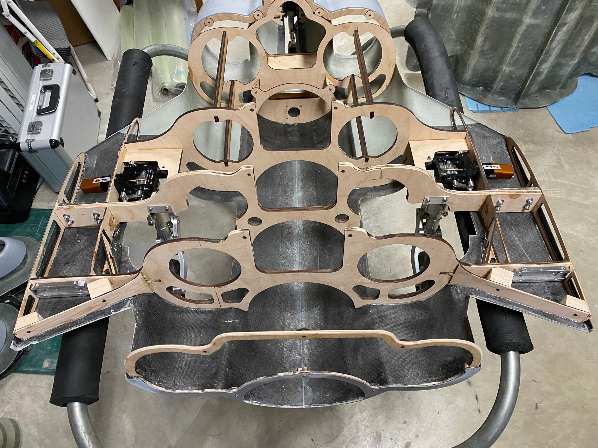
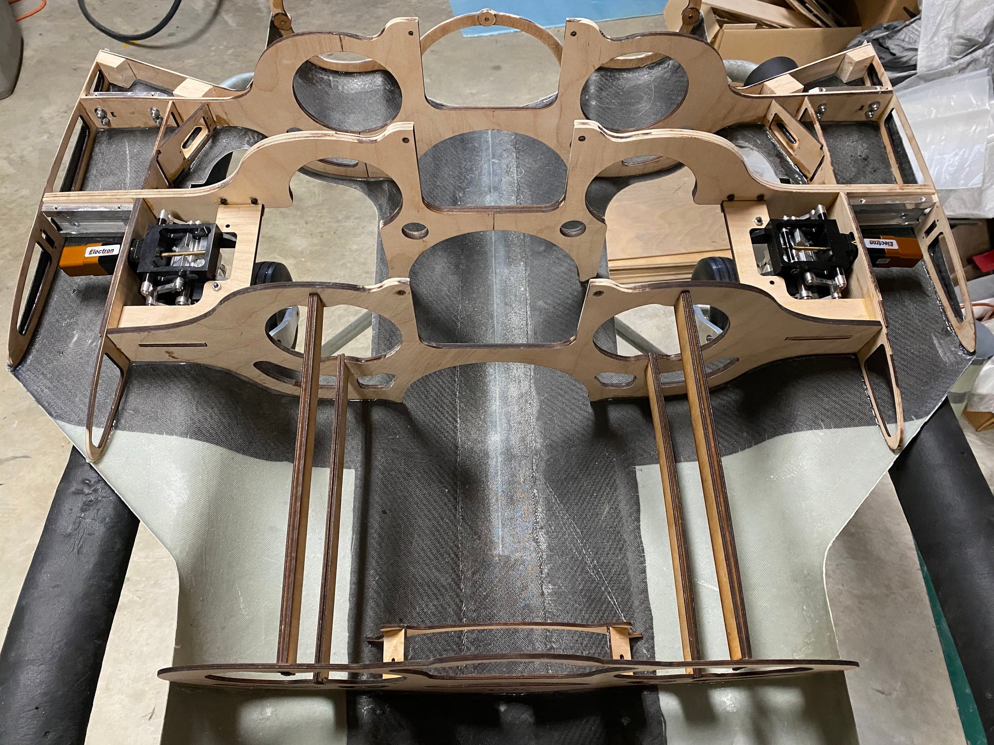
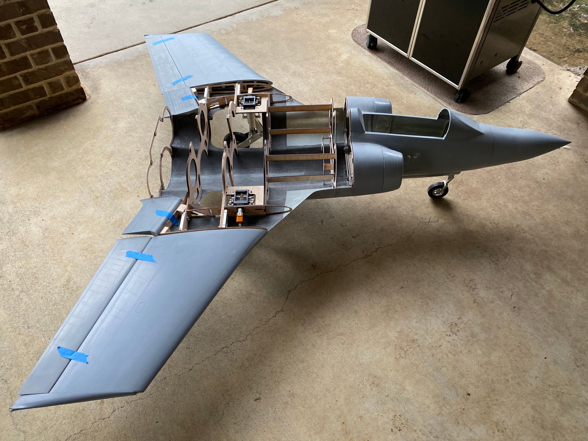
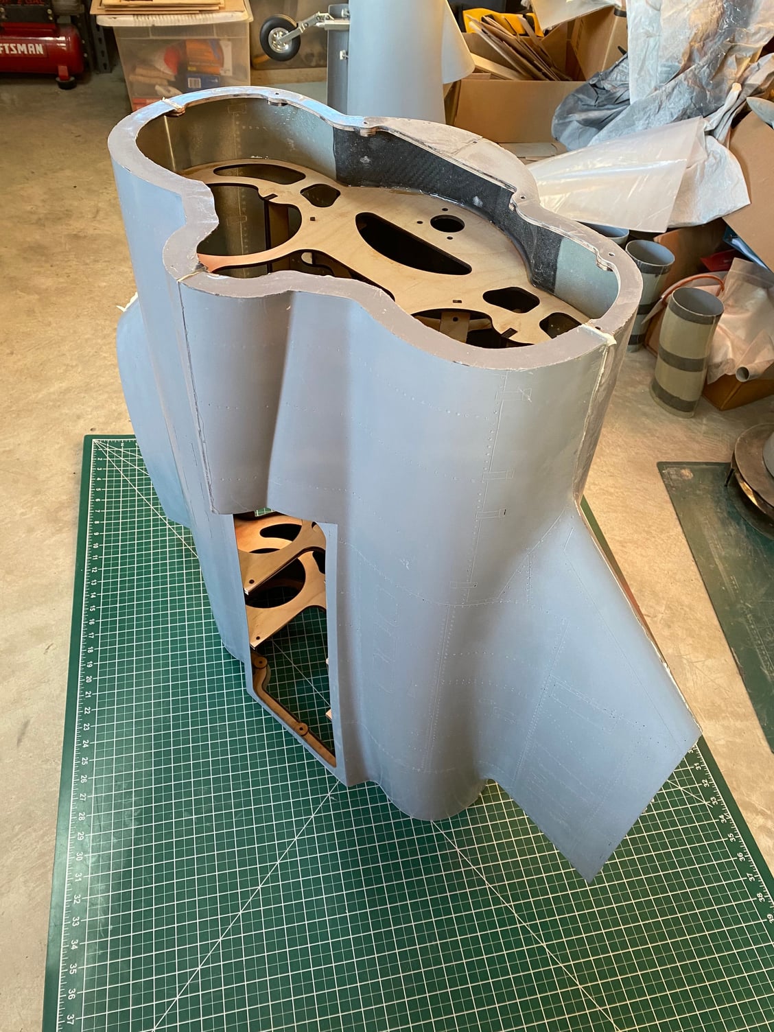
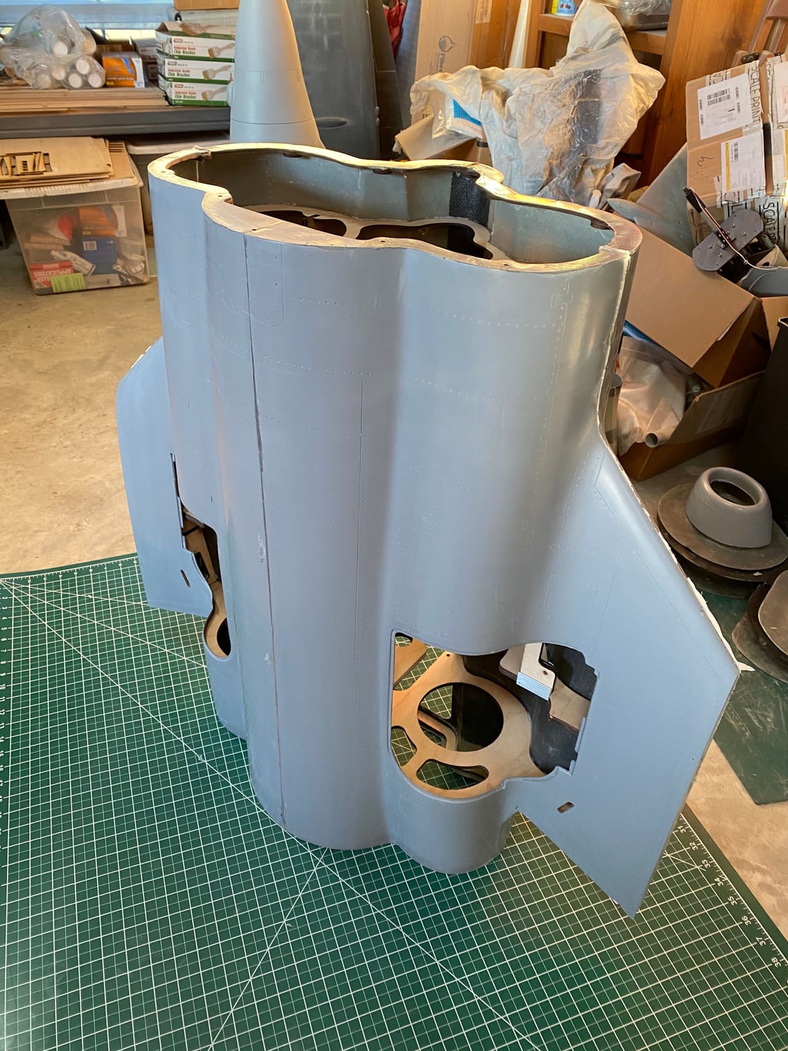
I've been working on the center fuselage. I finalized all the structure and have bonded them into place on the lower skins.
I have some more fitting out to do before I'll be ready to close it up and bond on the upper skin.
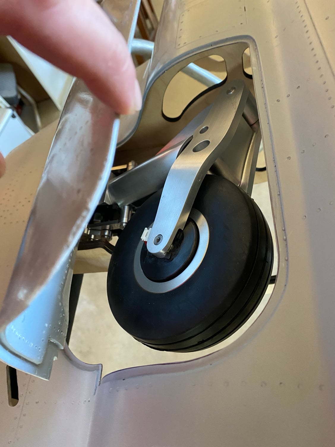
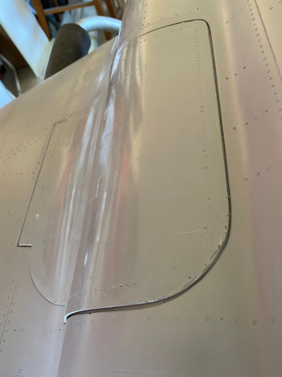
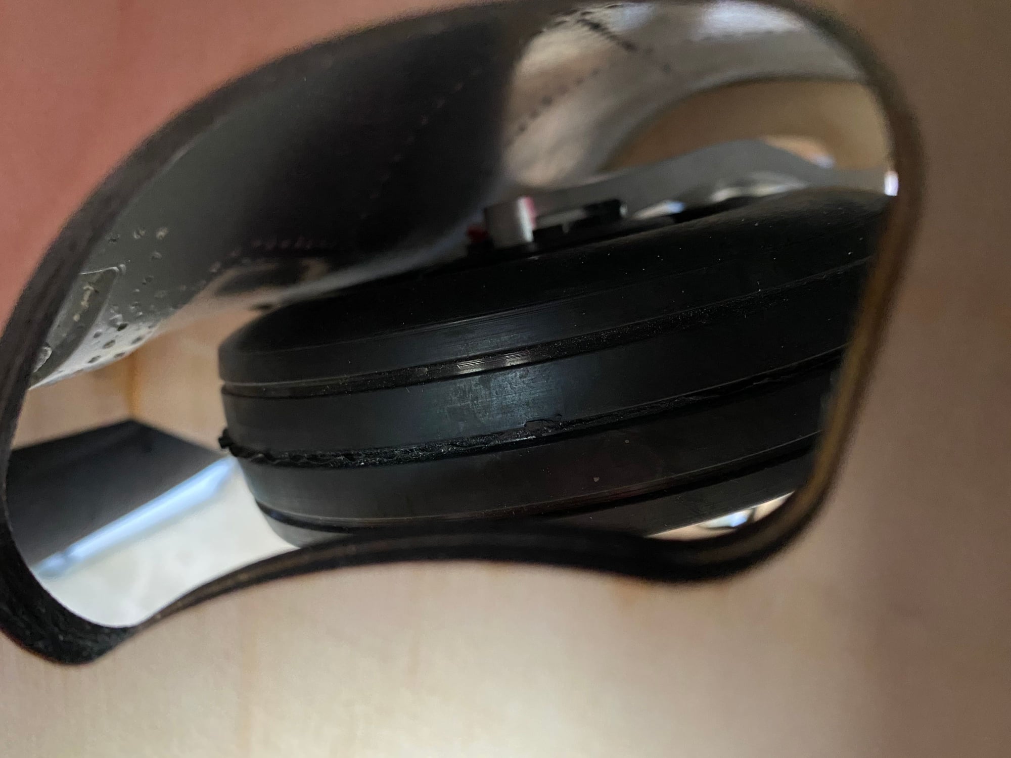
Test fit of the gear went well and they retract cleanly and the main doors fit well. I'll also hinge the main doors before adding the upper skin.
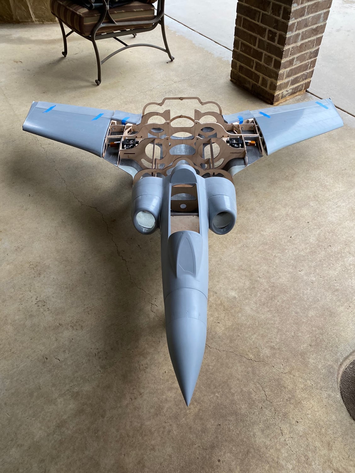
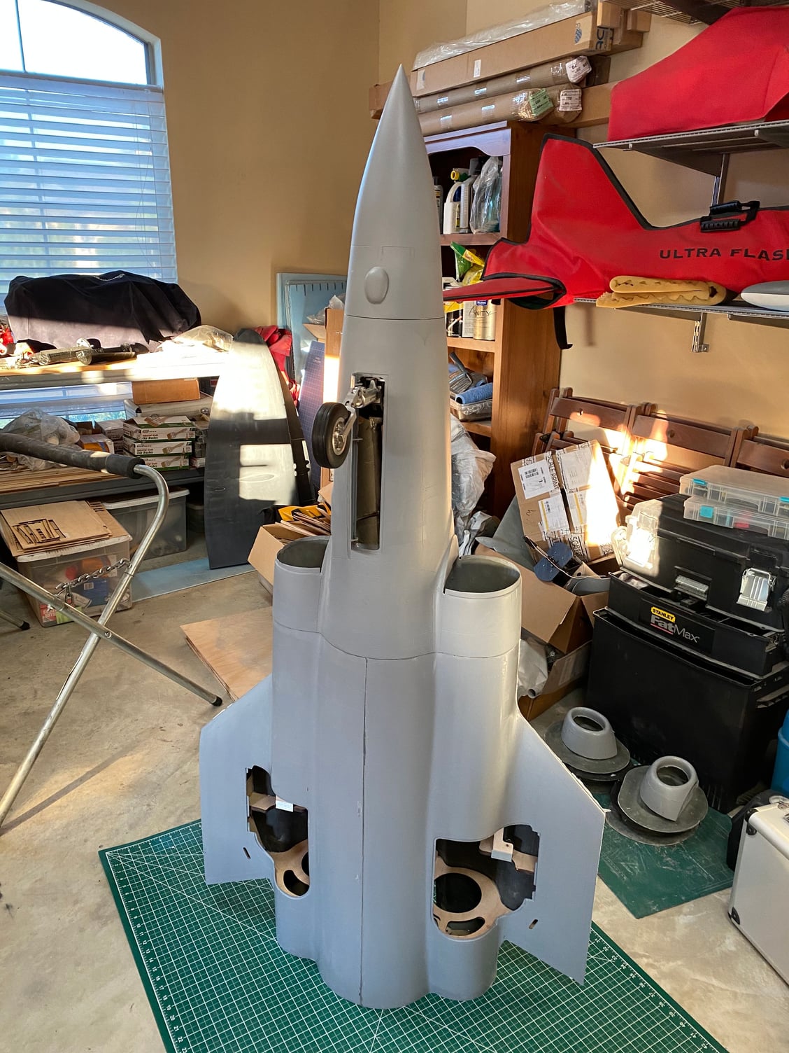
I did a test assembly and had it on the gear for the first time. It is starting to look like a real aircraft.
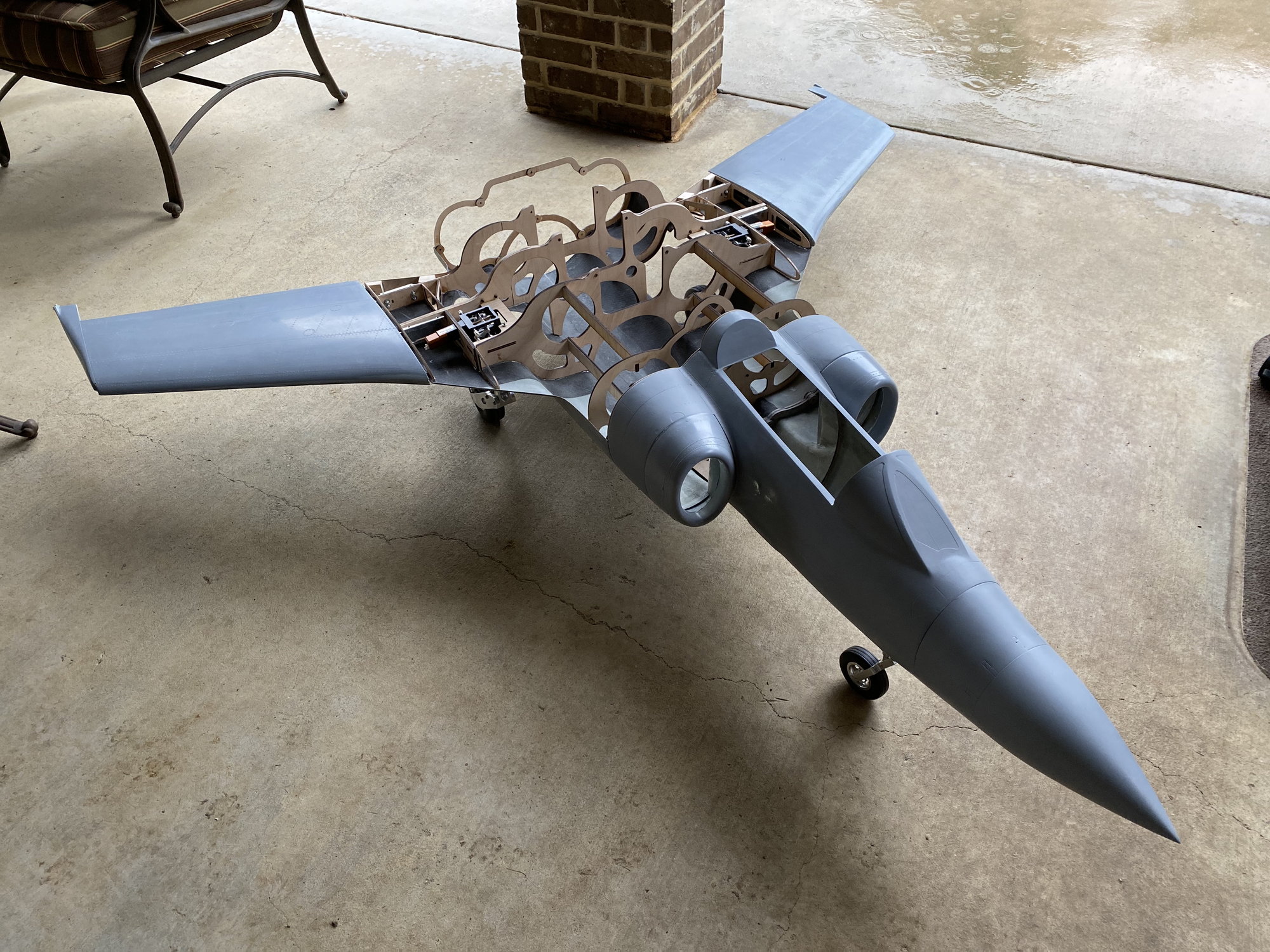
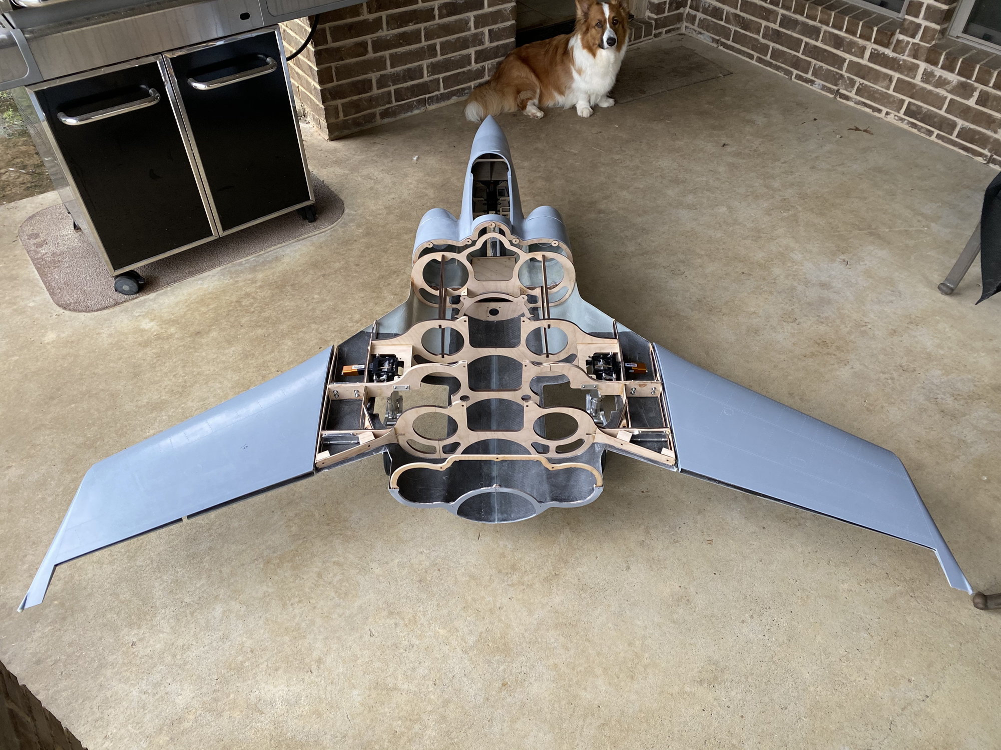
The wing area looks a bit more respectable with the flaps and flaperons in place.
Paul
I have some more fitting out to do before I'll be ready to close it up and bond on the upper skin.
Test fit of the gear went well and they retract cleanly and the main doors fit well. I'll also hinge the main doors before adding the upper skin.
I did a test assembly and had it on the gear for the first time. It is starting to look like a real aircraft.
The wing area looks a bit more respectable with the flaps and flaperons in place.
Paul
The following 2 users liked this post by JSF-TC:
Andrew Bird (05-18-2020),
pilot43 (05-18-2020)


 05-23-2020, 10:47 AM
#410
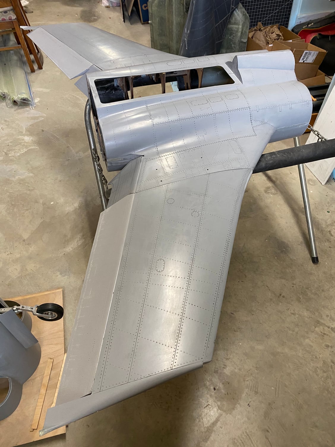
Been working on more of the little details in the center fuselage. This is now more like a normal kit build.
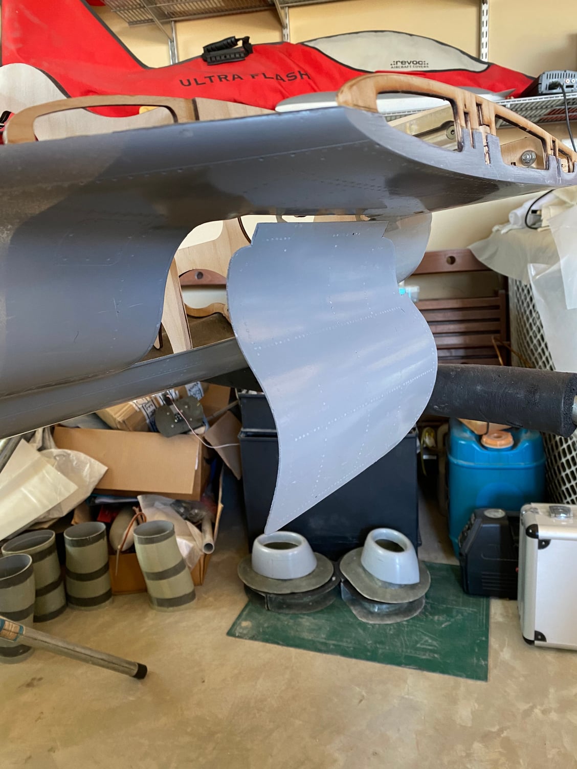
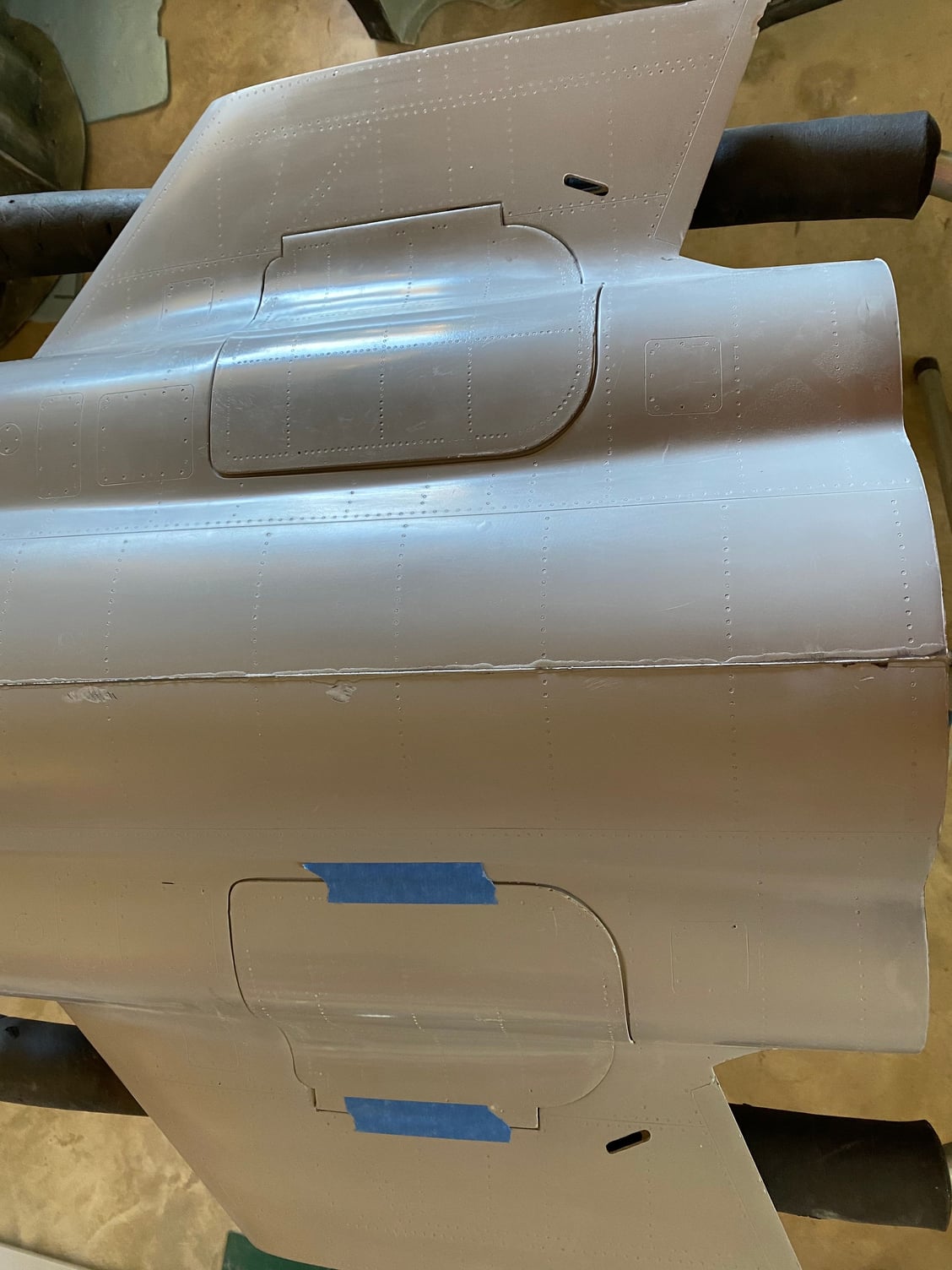
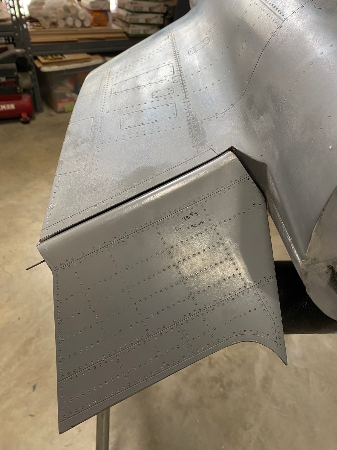
Hinged all of the control surfaces; flaps and flaperons.
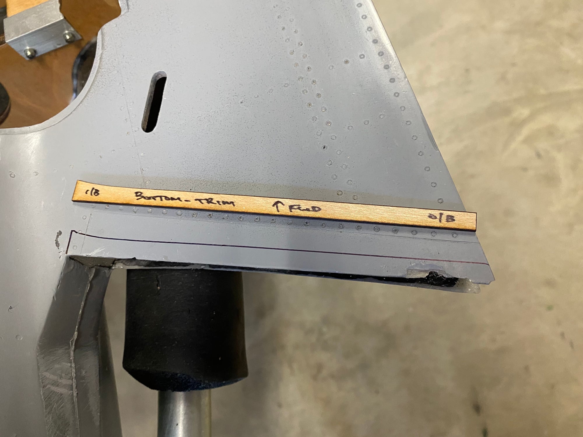
To determine the control surface gap shroud cut lines, I used the CAD model with deflected control surfaces to define the edge, then I laser cut the template for the flap cut lines as it wasn't a straight line cut. The flaperons were a simple straight line I could just use a ruler to mark them out. After cutting the shrouds, some sandpaper around the leading edge of the control surface allowed them to be beveled and fared in to form a sharp edge. Carbon had been laid in the parts to give a hard resilient sharp edge.
Wing joiners were also permanently glued in to the wings. The whole structure when assembled feels incredibly stiff.
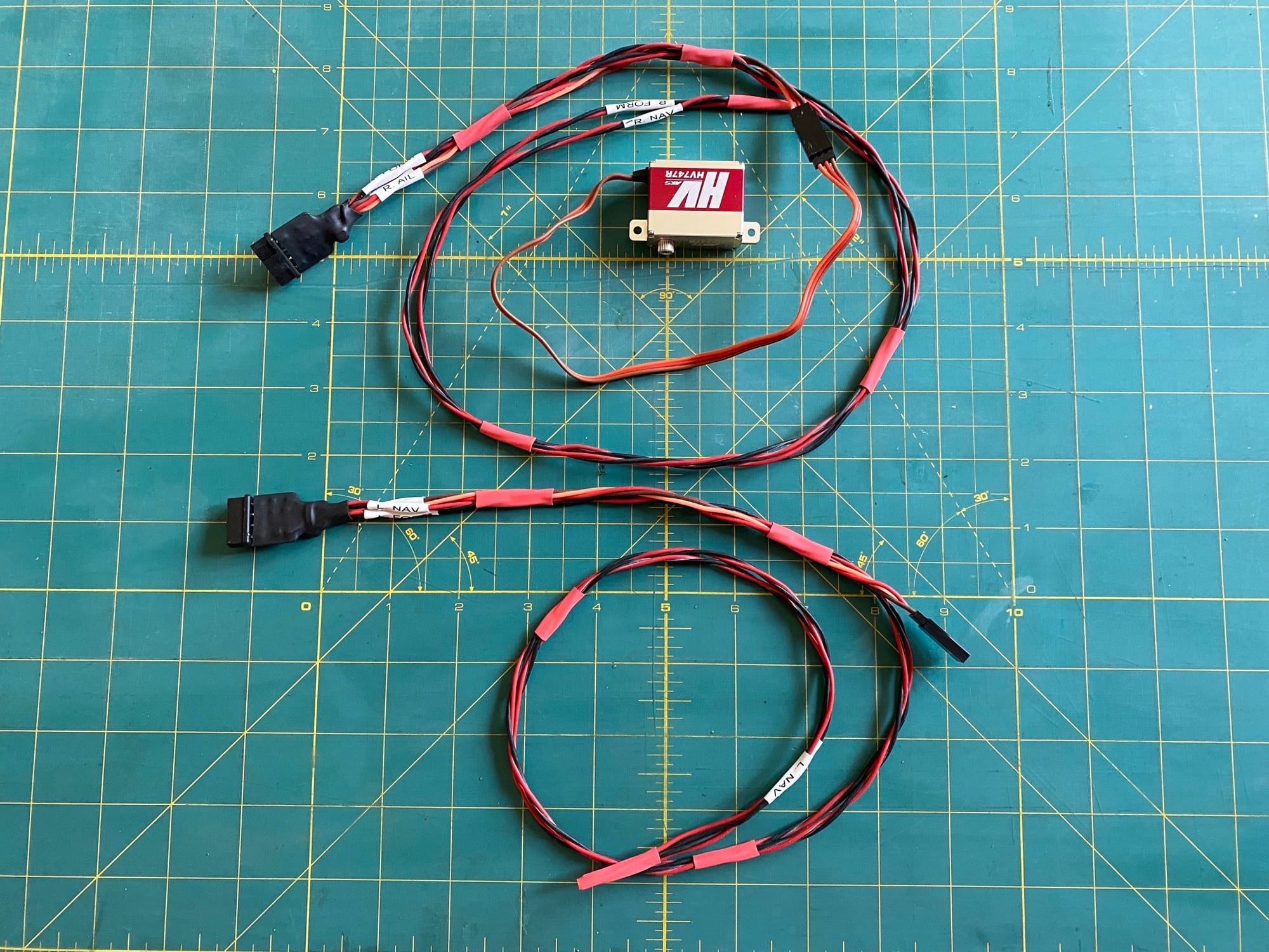
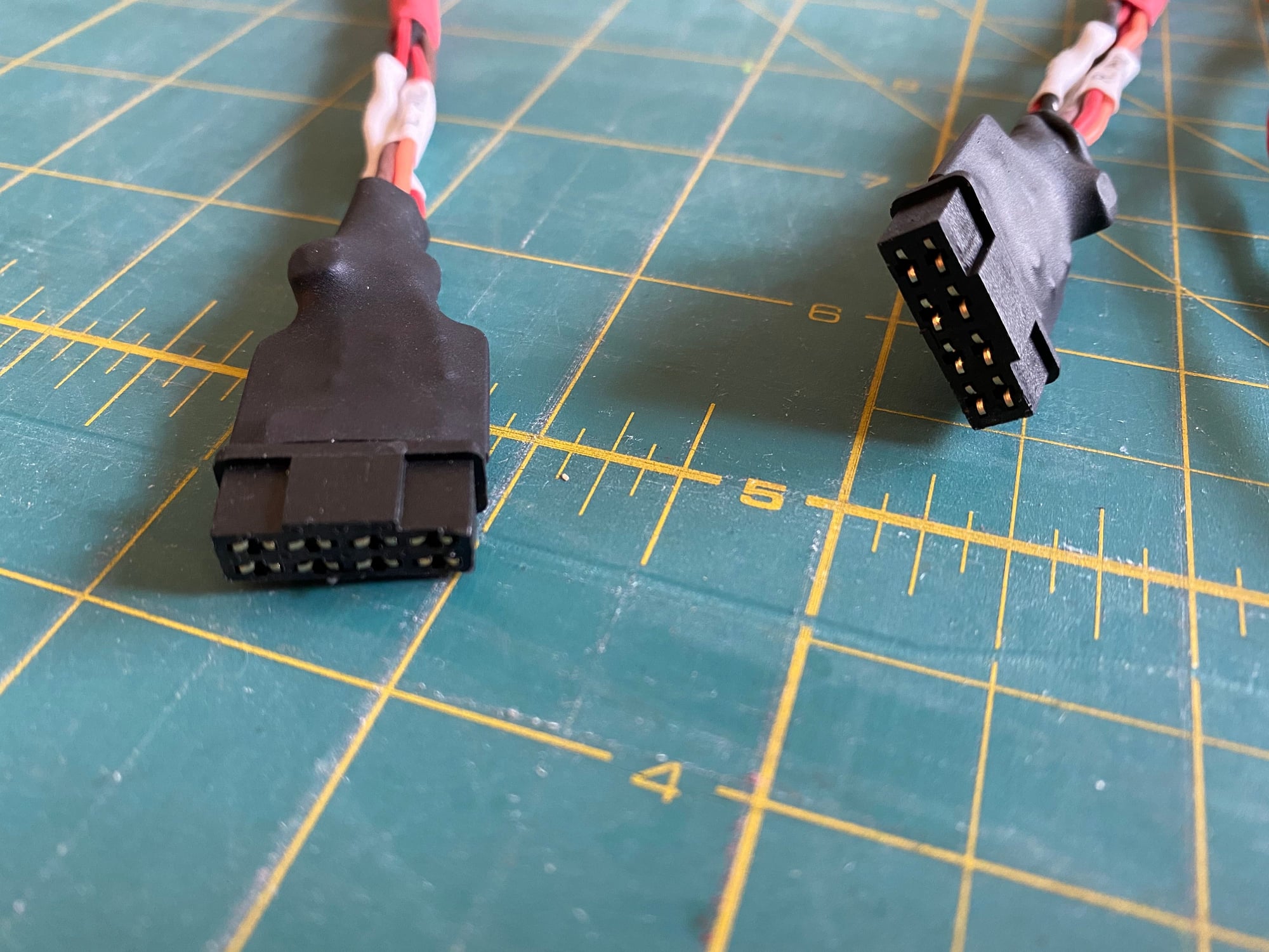
For a change of pace, I have also made up the wing wiring harnesses. 1 servo and 2 lights. Emotec 8-pin connectors are used for the wing disconnect with the fuselage bulkhead connector mount designed into the root rib.
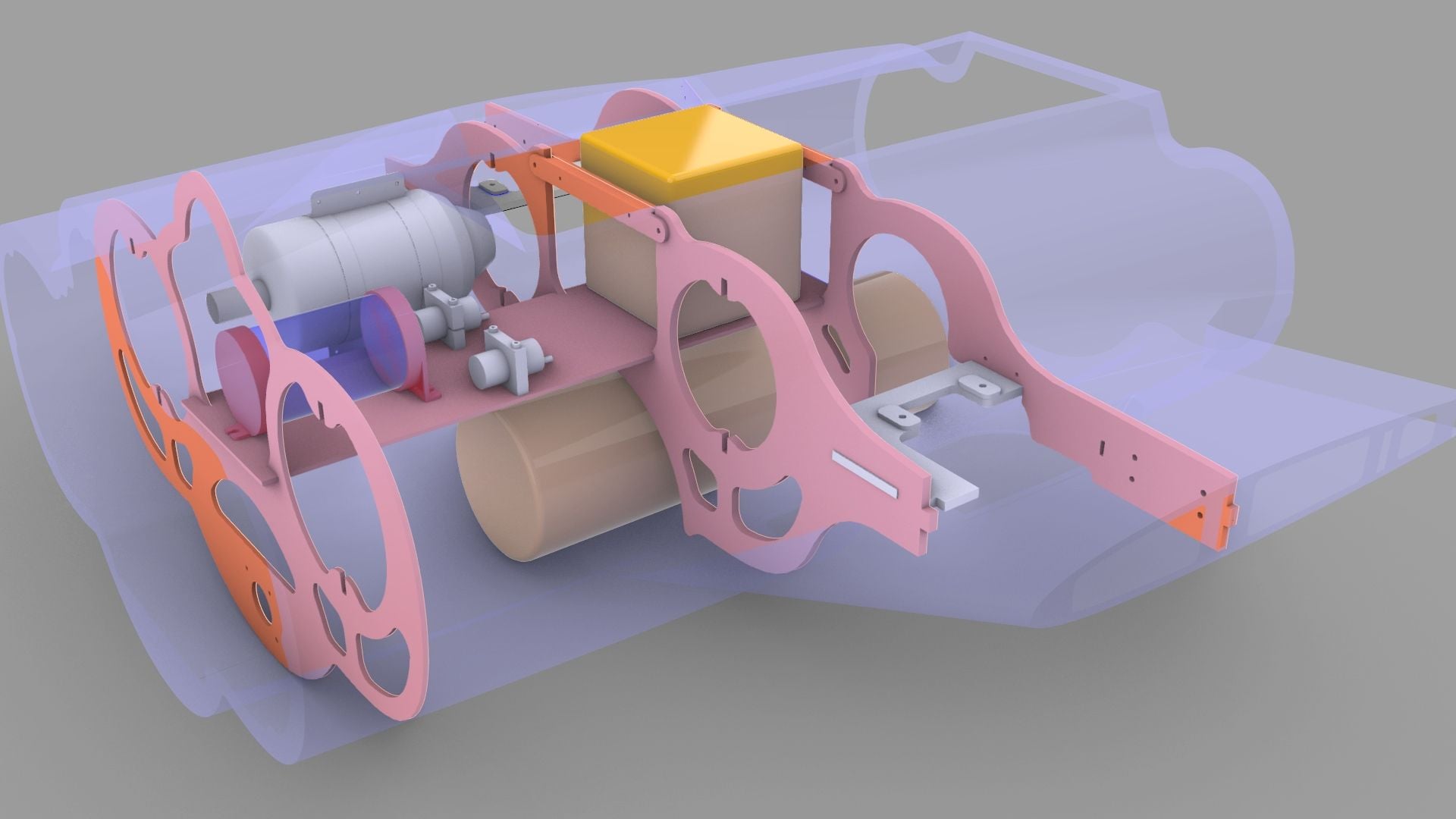
For the initial flights I decided to skip the rotating weapon bay fuel tank and instead I ordered 2 custom tanks from Gary at Jet Tech. Placed exactly at the c.g, they total 176oz, which should give me at least an 8 min flight time base on my 120oz in my 140 powered Hunter. I can easily retro-fit the rotating weapon bay later. The 50oz header tank will feed the air trap as a secondary means of containing any air getting to the engines.

Paul
Hinged all of the control surfaces; flaps and flaperons.
To determine the control surface gap shroud cut lines, I used the CAD model with deflected control surfaces to define the edge, then I laser cut the template for the flap cut lines as it wasn't a straight line cut. The flaperons were a simple straight line I could just use a ruler to mark them out. After cutting the shrouds, some sandpaper around the leading edge of the control surface allowed them to be beveled and fared in to form a sharp edge. Carbon had been laid in the parts to give a hard resilient sharp edge.
Wing joiners were also permanently glued in to the wings. The whole structure when assembled feels incredibly stiff.
For a change of pace, I have also made up the wing wiring harnesses. 1 servo and 2 lights. Emotec 8-pin connectors are used for the wing disconnect with the fuselage bulkhead connector mount designed into the root rib.
For the initial flights I decided to skip the rotating weapon bay fuel tank and instead I ordered 2 custom tanks from Gary at Jet Tech. Placed exactly at the c.g, they total 176oz, which should give me at least an 8 min flight time base on my 120oz in my 140 powered Hunter. I can easily retro-fit the rotating weapon bay later. The 50oz header tank will feed the air trap as a secondary means of containing any air getting to the engines.
Paul
The following users liked this post:
Daveeast (05-30-2020)
06-04-2020, 07:05 AM
#411
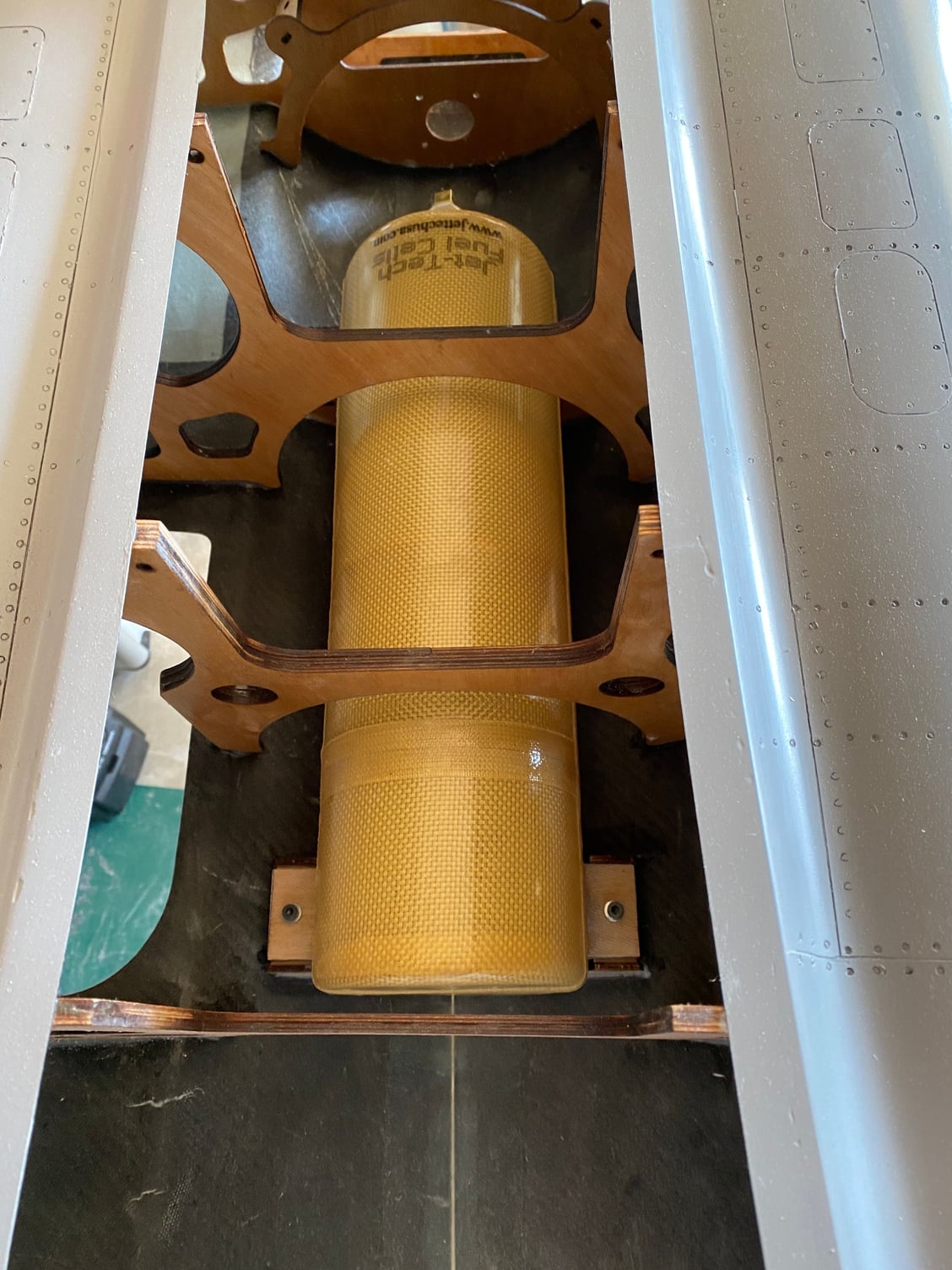
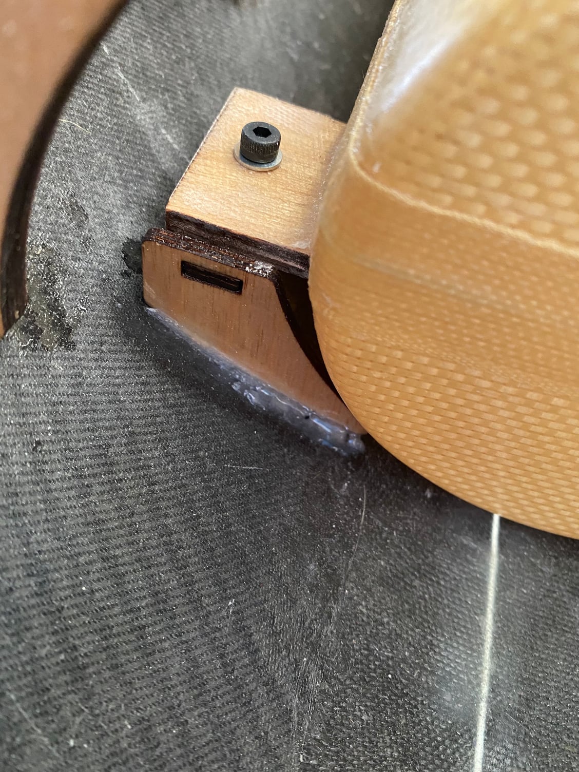
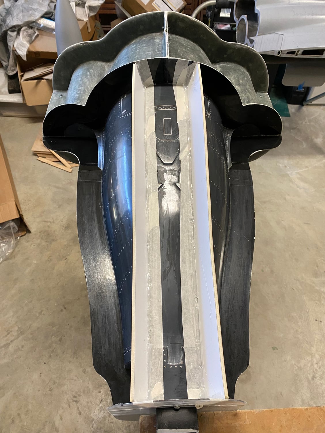
I've installed the main fuel tank, which I received from Gary at JetTech. Held in with four bolts into captive nuts in the tank mounts it can be removed once the rear fuselage has been removed. The hopper tank will be mounted above it at a later date.
I have also been working on the rear fuselage molds. The first 4 pieces are complete. I think this will end up as a 9 piece mold to avoid any risk of parts being trapped.

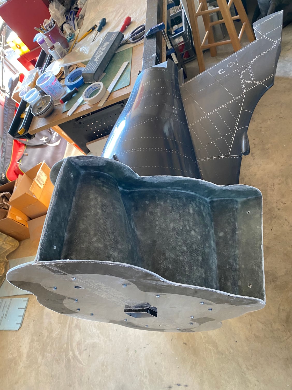
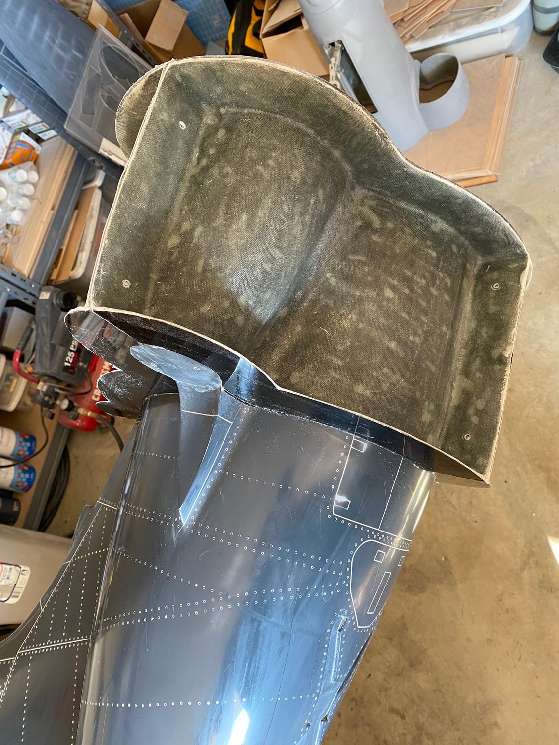
I have also been working on the rear fuselage molds. The first 4 pieces are complete. I think this will end up as a 9 piece mold to avoid any risk of parts being trapped.
06-09-2020, 07:16 PM
#412
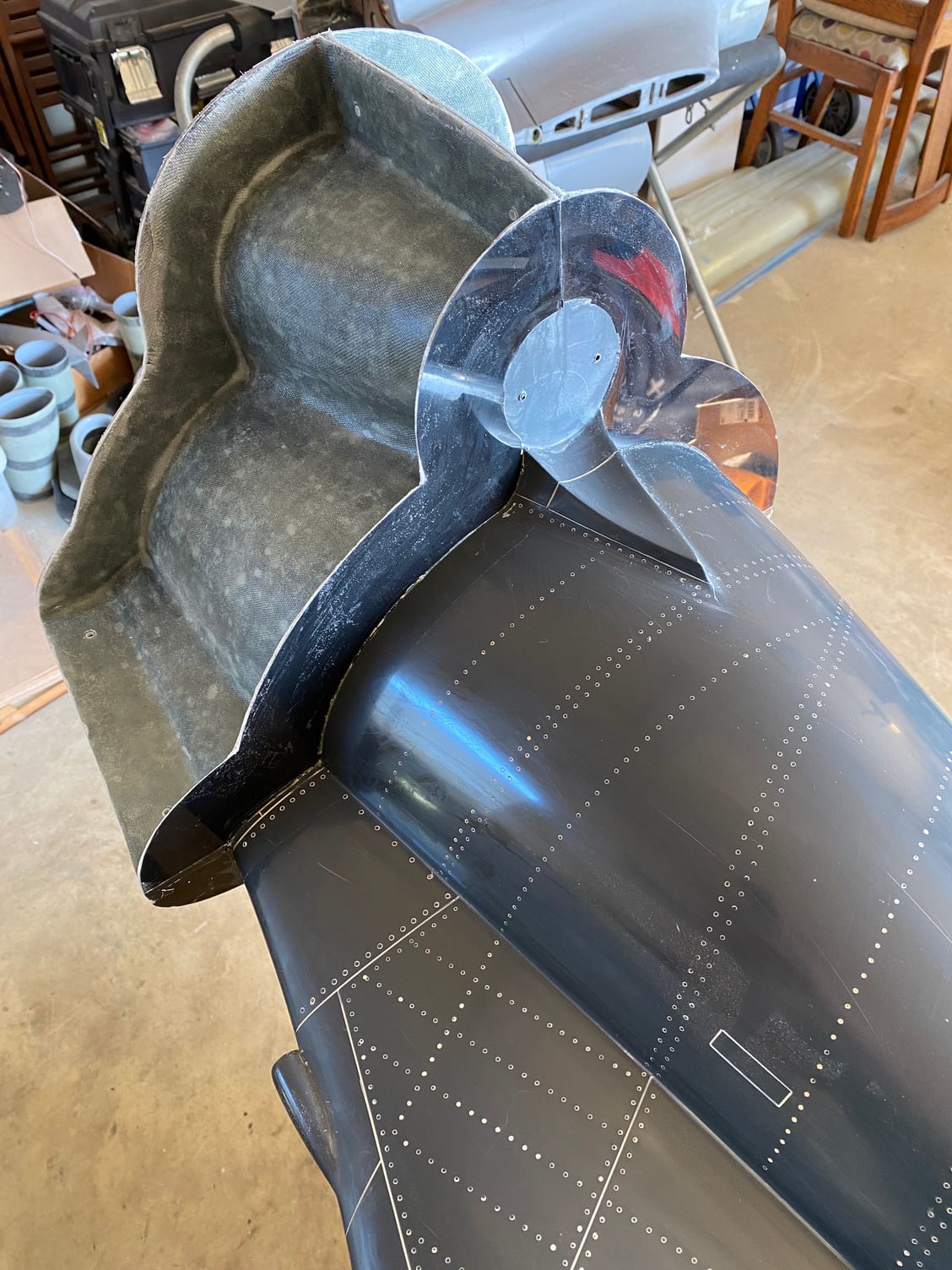
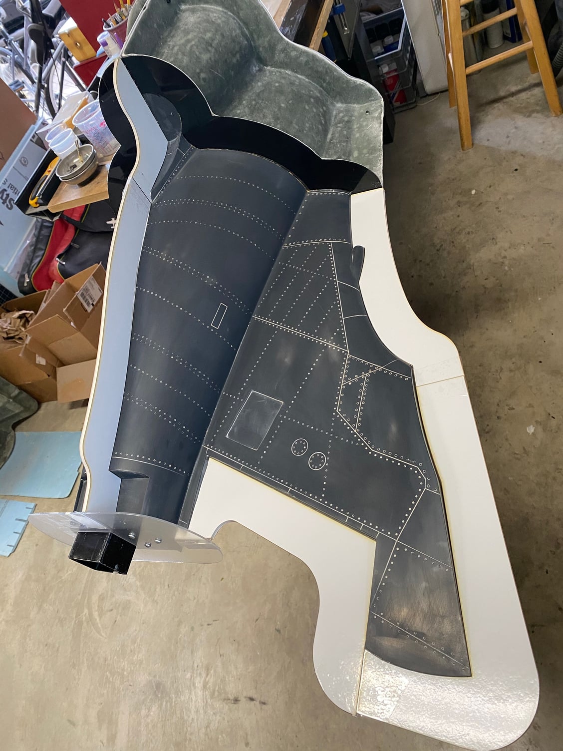
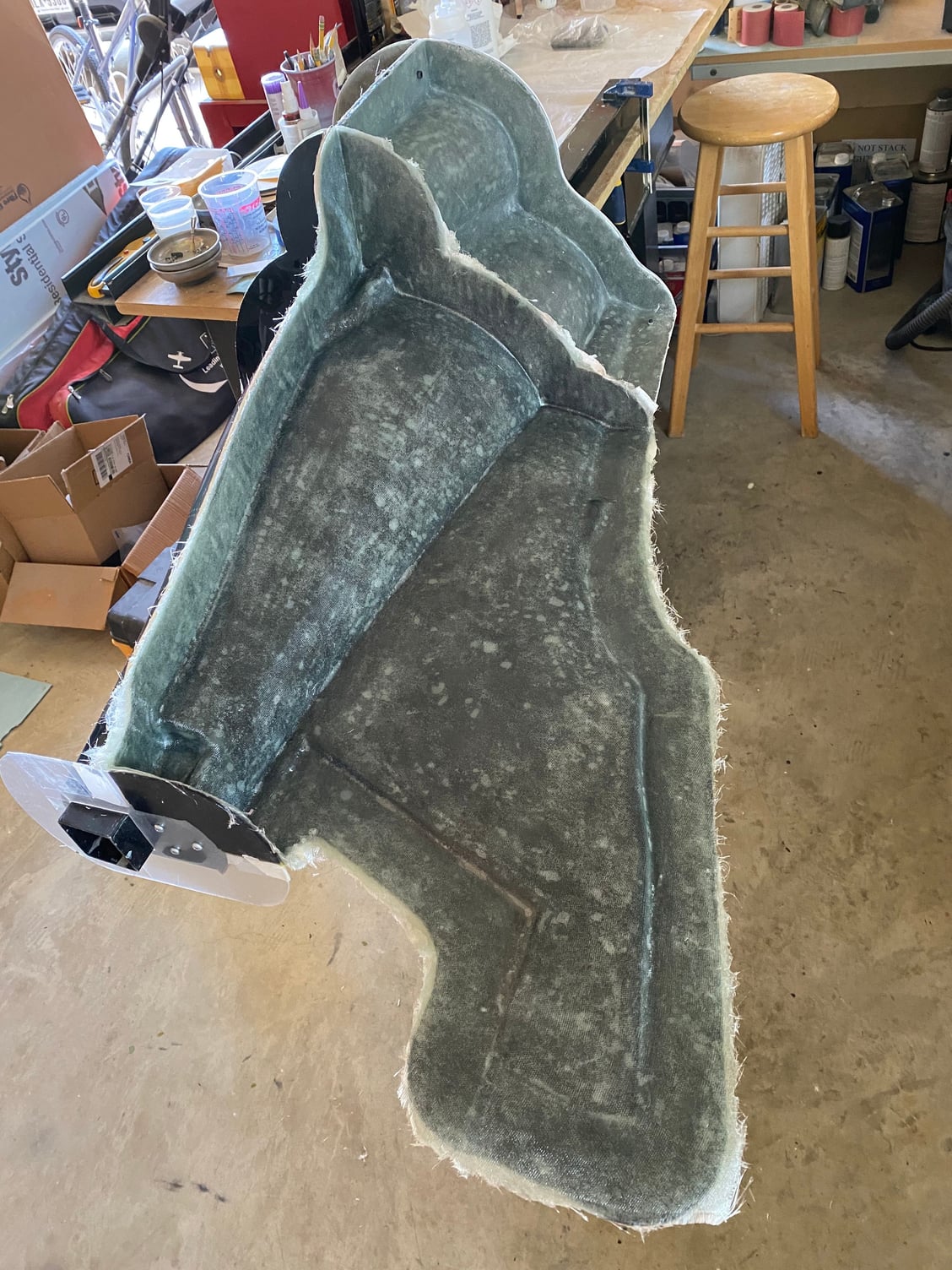
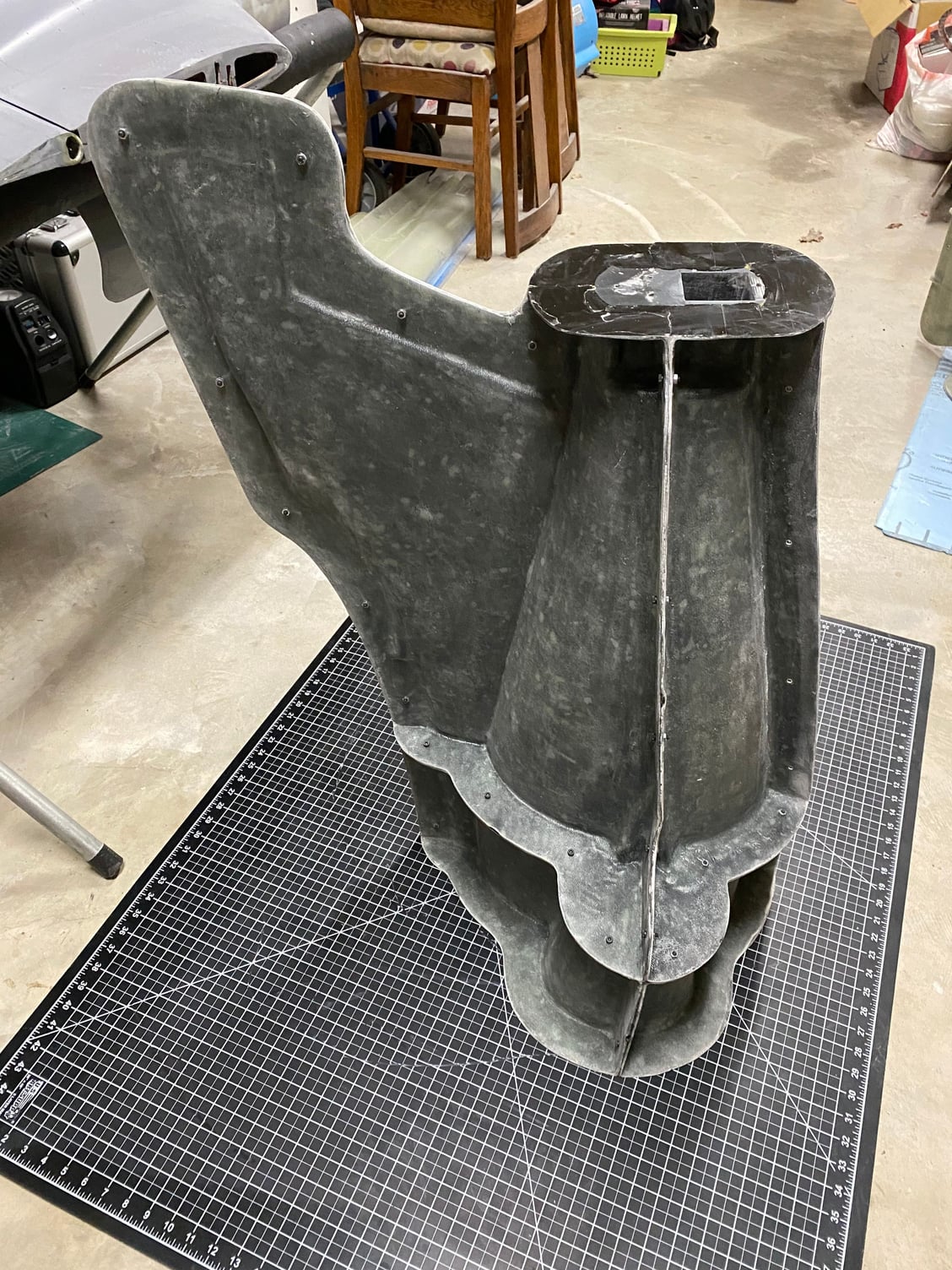
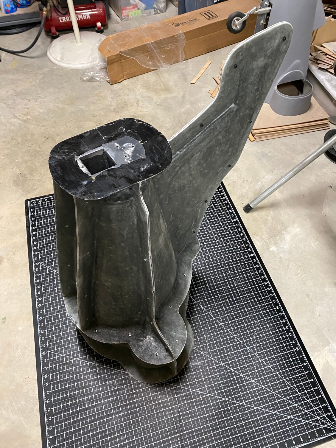
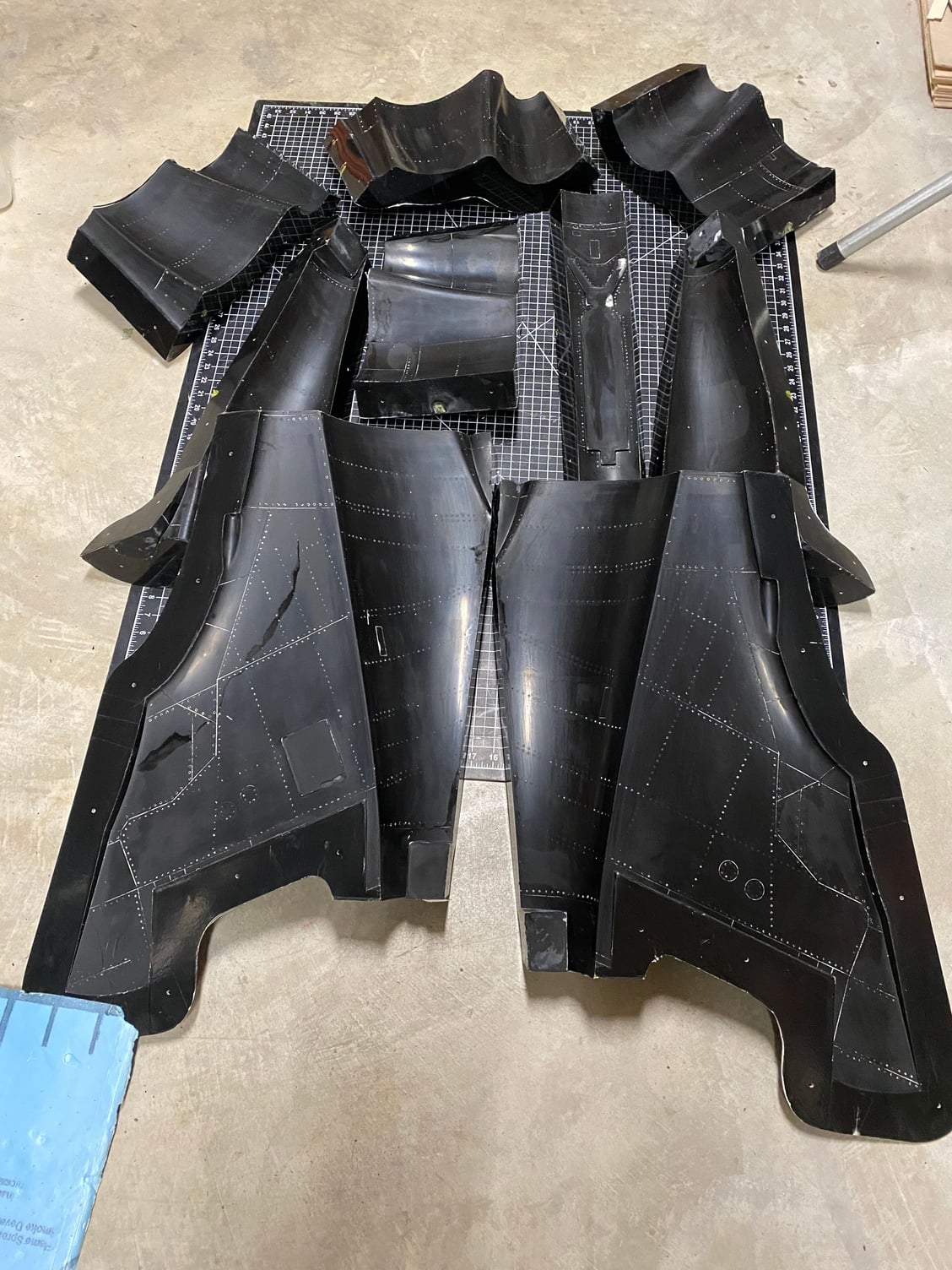
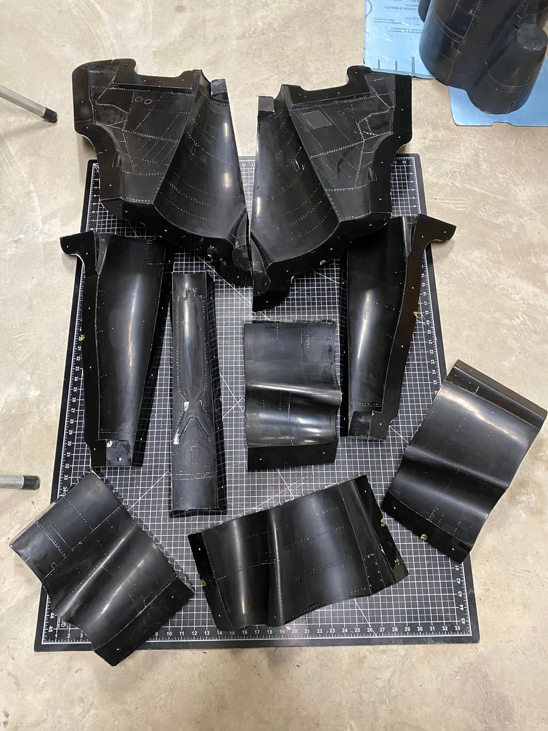
After what seemed like ages, but not much more than a week I have finished the molds for the rear fuselage. It ended up as a 9 piece mold, each one individually laid up and trimmed before progressing to the next. Just a few random photos from the construction sequence attached below.
I opened up the molds tonight and they came away without a fight. Just a minor chip in the lower section inside the tail bumper and arrestor hook recess, so this will be easy to repair.
This was by far the most complex mold set in this project. The fuselage has taken 23 mold pieces from the tip of the radome to the tip of the speedbake, excluding the 2 hatches which I still have to make.
Time to clean up the molds and assemble them into the 3 discrete sections (left upper, right upper and lower) to start making the flying parts.
Last edited by JSF-TC; 06-09-2020 at 07:26 PM.
06-12-2020, 07:27 AM
#413
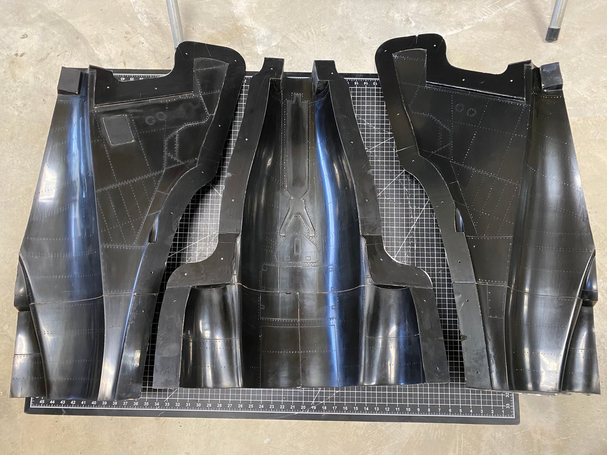
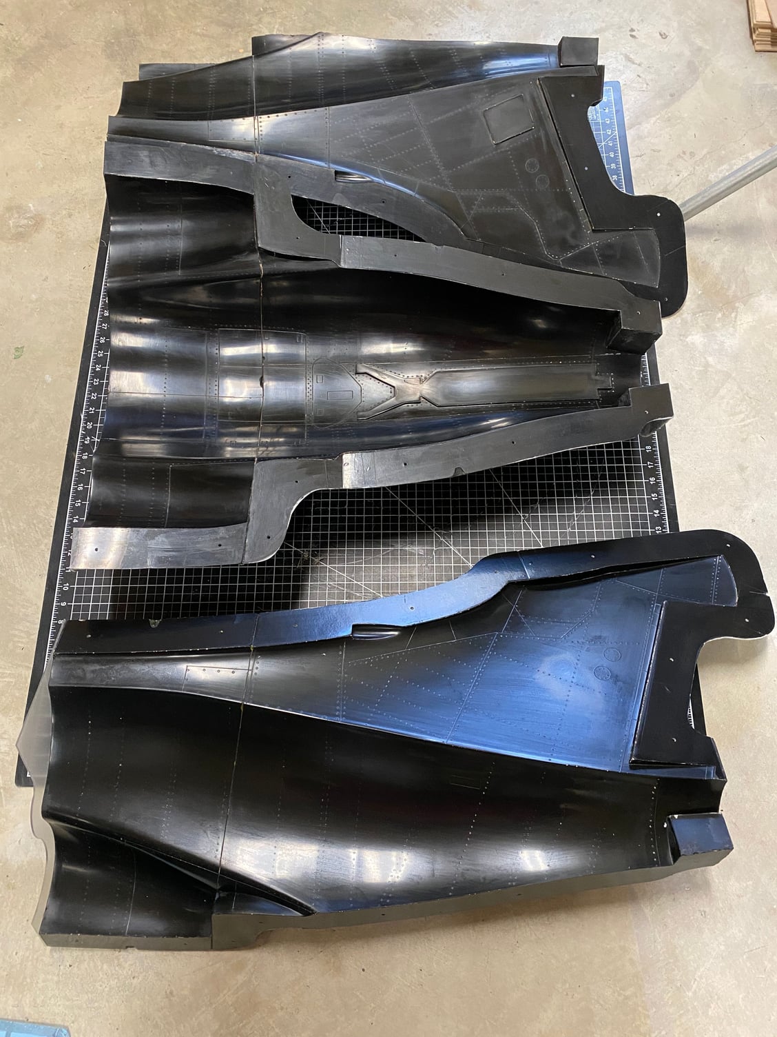
Molds cleaned, a couple of minor chips repaired and then polished and assembled into the 3 main sub-assemblies. After assembly I spotted one more chip that needs repair in the bottom mold set.
The first piece was laid up and pulled out of the mold this morning. All I can say is Wow!!! I'm super impressed with how it turned out. It looks almost professional. The opposite side is in work to be laid up today.


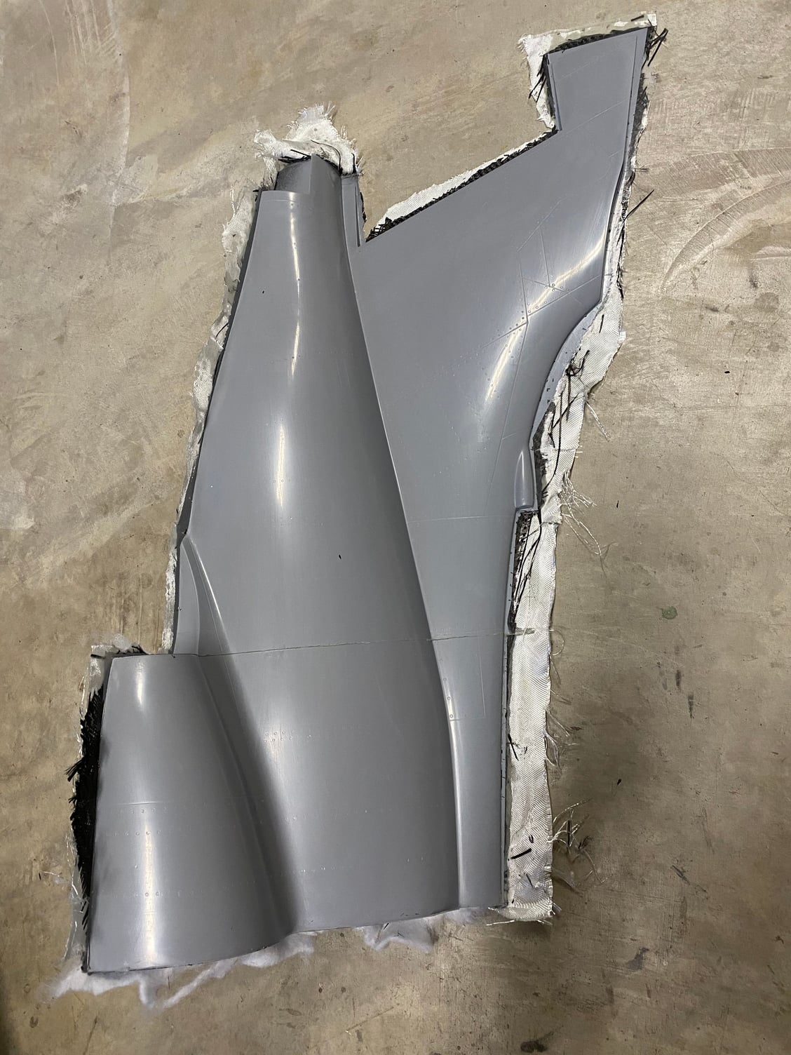
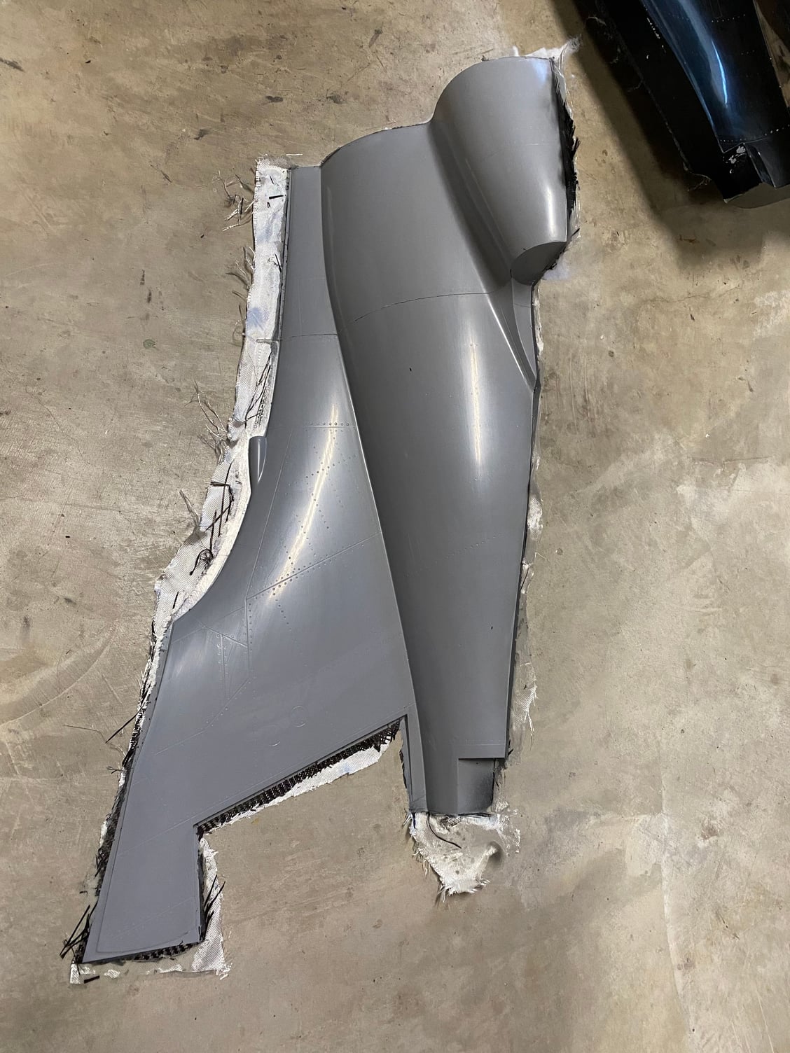
The first piece was laid up and pulled out of the mold this morning. All I can say is Wow!!! I'm super impressed with how it turned out. It looks almost professional. The opposite side is in work to be laid up today.
06-12-2020, 09:21 AM
#414

Can you explain a bit to those of us who don't understand the full process what the products and purposes are in a couple of those last pics? Right after the pic of all your carbon and glass, there is the mold with what looks like a heavy coat of grey primer, then a heavy coat of white something - or is that just the wetted out glass?
When you lay your glass in the mold, do you do multiple layers of a lighter cloth or one layer of a heavier cloth?
This is so cool to watch, just trying to understand the steps as much as I can while I watch.
When you lay your glass in the mold, do you do multiple layers of a lighter cloth or one layer of a heavier cloth?
This is so cool to watch, just trying to understand the steps as much as I can while I watch.
06-12-2020, 09:37 AM
#415
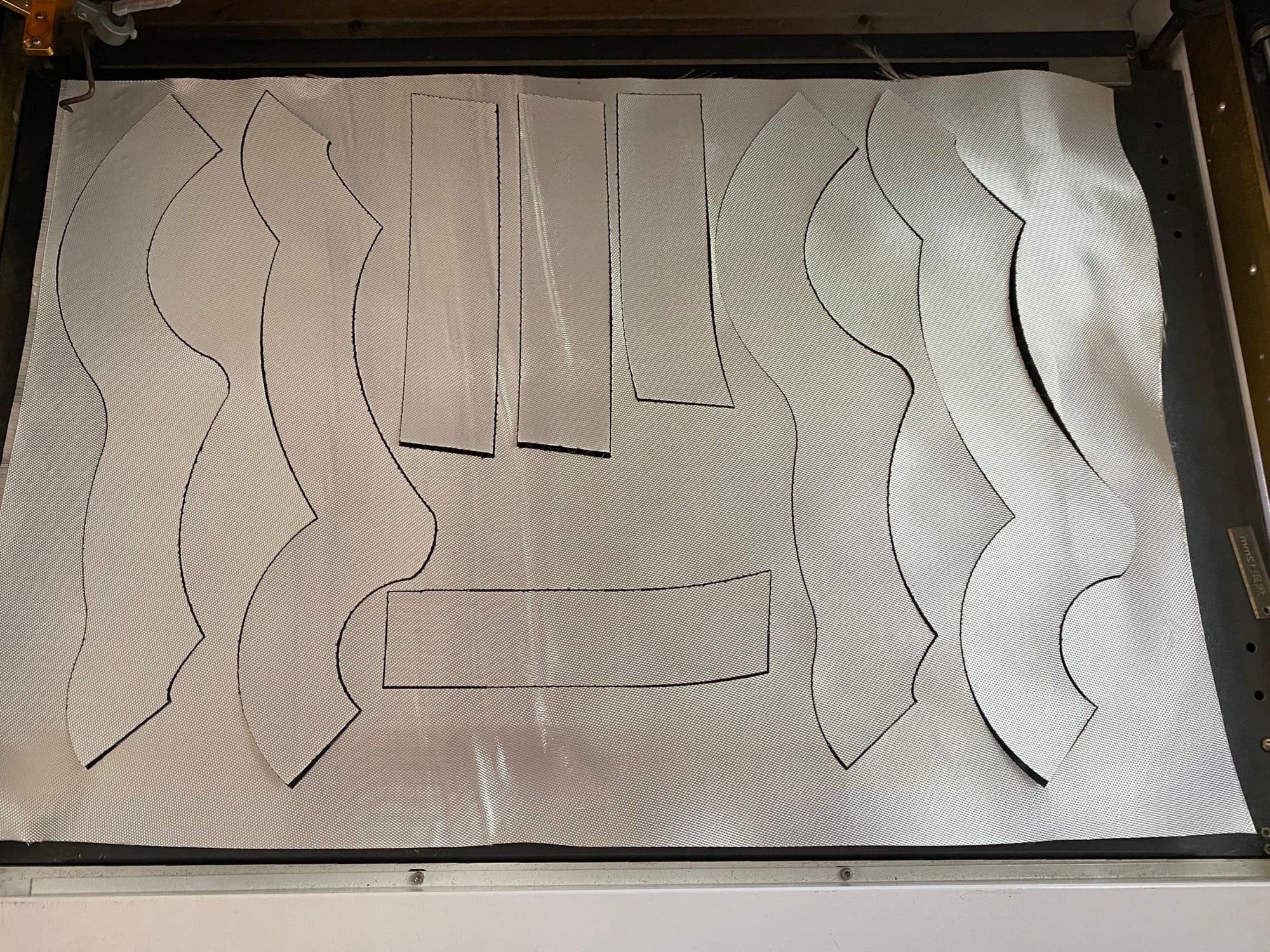
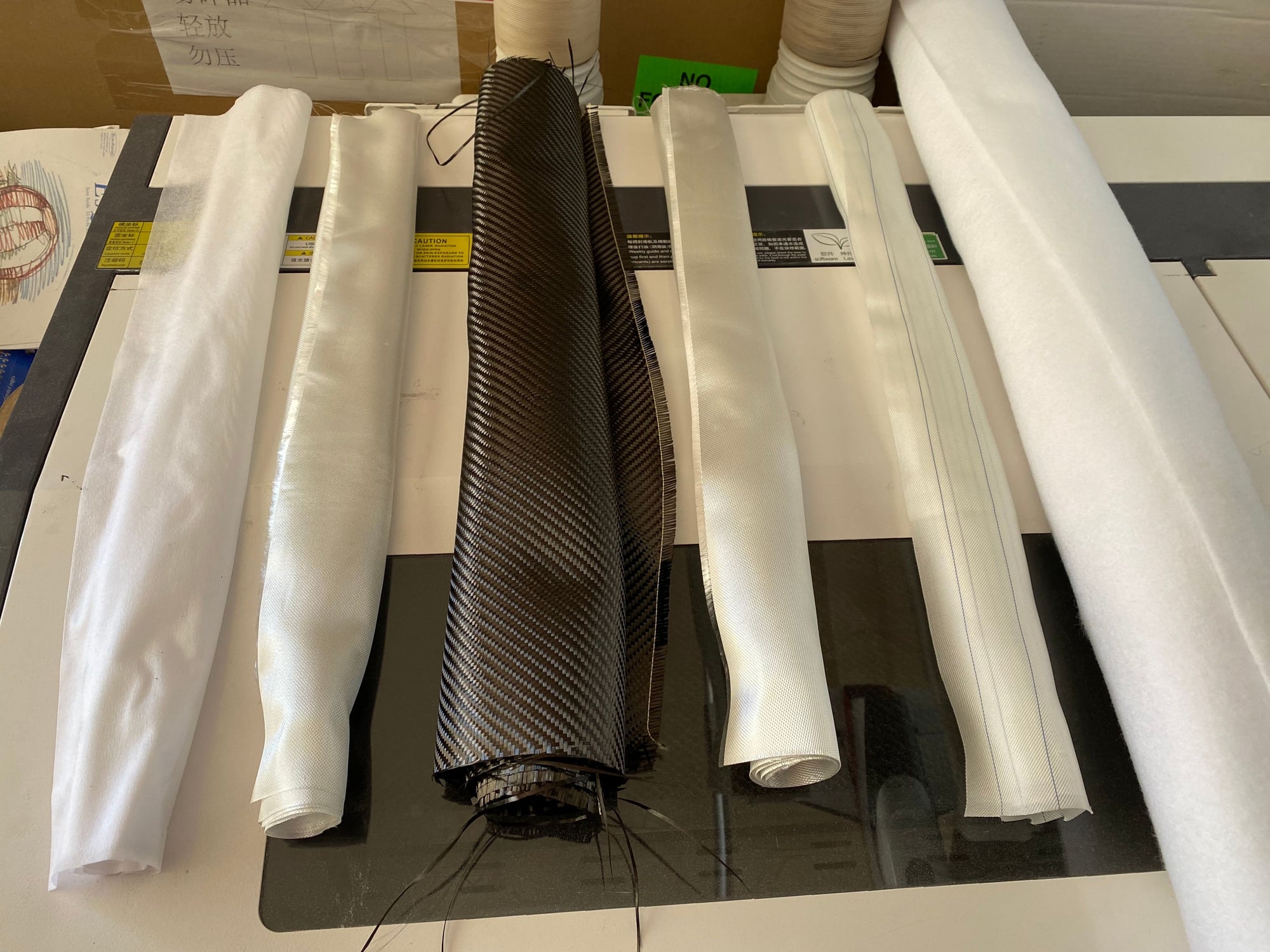
OK, to answer the above question, lets start with this photo;

They are arranged in order of application. From left to right we have;
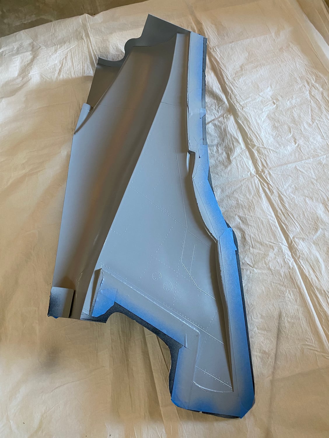
Once the release agent is applied (Frekote) I spray the epoxy (Klass-Kote) grey primer and let it flash off. That is this photo;
I then fill in any sharp edges with a thickened bead of epoxy and apply the surface veil, wetting it out thoroughly. This stage shown below.
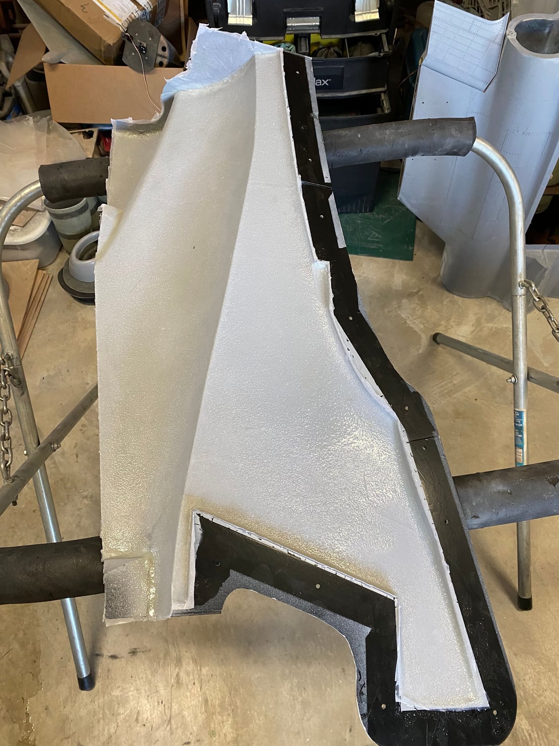
This stage is then allowed to partially cure to the 'green', tacky stage before laying down the 3oz, carbon and 9oz cloth. I found wetting the surface with the epoxy and then laying down the glass and let it soak through works best, rather than forcing the epoxy down into the dry glass. The last layer (9oz) is applied with minimal additional resin as it will soak up through as it is compressed under vacuum.
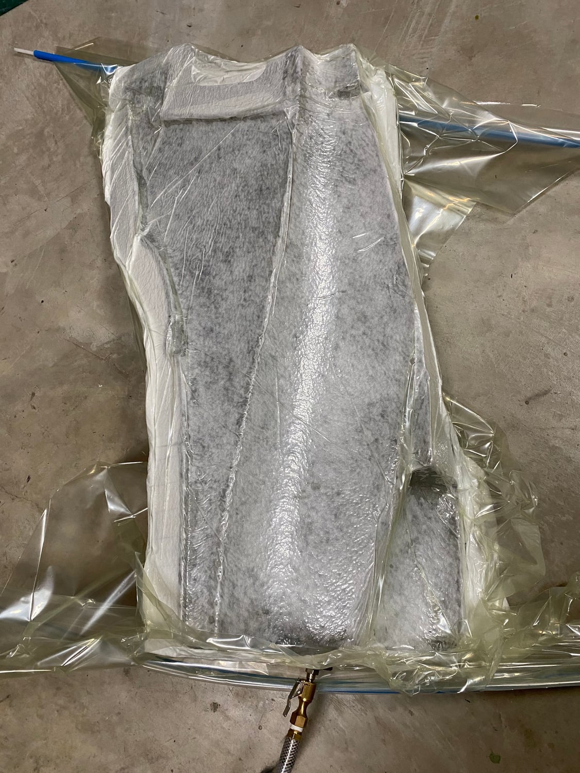
Once the glass/ carbon/ glass is applied, the peel ply is then laid over, followed by the breather fabric which will soak up any excess resin as it is squeezed under vacuum. I wrap the entire mold in the bleeder fabric to protect the vacuum bag form any sharp edges and then place in the bag and suck it down with a vacuum pump. This part is shown below.

If it all works well, you end up with a decent finished part the next morning!
Hope that helps - I'm finding that I'm enjoying this build process much more than carving/ planking/ sanding balsa for the traditional construction methods.
Paul
They are arranged in order of application. From left to right we have;
- Surface Veil
- 3oz twill weave glass cloth
- 6oz twill weave carbon cloth
- 9oz twill weave glass cloth
- Peel Ply
- Bleeder Fabric
Once the release agent is applied (Frekote) I spray the epoxy (Klass-Kote) grey primer and let it flash off. That is this photo;
I then fill in any sharp edges with a thickened bead of epoxy and apply the surface veil, wetting it out thoroughly. This stage shown below.
This stage is then allowed to partially cure to the 'green', tacky stage before laying down the 3oz, carbon and 9oz cloth. I found wetting the surface with the epoxy and then laying down the glass and let it soak through works best, rather than forcing the epoxy down into the dry glass. The last layer (9oz) is applied with minimal additional resin as it will soak up through as it is compressed under vacuum.
Once the glass/ carbon/ glass is applied, the peel ply is then laid over, followed by the breather fabric which will soak up any excess resin as it is squeezed under vacuum. I wrap the entire mold in the bleeder fabric to protect the vacuum bag form any sharp edges and then place in the bag and suck it down with a vacuum pump. This part is shown below.
If it all works well, you end up with a decent finished part the next morning!
Hope that helps - I'm finding that I'm enjoying this build process much more than carving/ planking/ sanding balsa for the traditional construction methods.
Paul
06-12-2020, 11:43 AM
#418
Dave,
Yes, I have. I'm keeping a detailed weight and balance spreadsheet. I'm still tracking to a finished weight of just over 50lb.
The center fuselage and wings with control surfaces, 4 servos and doors weighs in at 6200g (13lb 10oz).
For the fwd and center fuselage I was using 2 layers of 9oz glass which worked well, but I decided to reduce one of those down to 3oz to try to save some weight in the tail area.
Paul
 06-12-2020, 01:33 PM
#420

Dave,
Yes, I have. I'm keeping a detailed weight and balance spreadsheet. I'm still tracking to a finished weight of just over 50lb.
The center fuselage and wings with control surfaces, 4 servos and doors weighs in at 6200g (13lb 10oz)
For the fwd and center fuselage I was using 2 layers of 9oz glass which worked well, but I decided to reduce one of those down to 3oz to try to save some weight in the tail area.
Paul
So just just under 60lb take off weight? I hope it does not creep up!
Dave
06-12-2020, 03:38 PM
#422
Thanks. All's good here. Hope you and your family are well.
It's all been kinda fun, but I'm now getting close to having a regular ARF to assemble.........
Dave,
Your comment made me go back and check a few assumptions, and I found a big flaw in my 50lb target weight.
In part, the 50lb target in the beginning was driven by an equivalent wing loading to my DerJet Hunter, in the order of 75oz/ sq. ft.
Unfortunately, I used the wet (take off) weight for the Hunter, and then said that was my dry weight target for the Buccaneer. Somehow I forgot the 10lb of fuel in those assumptions.
Anyway, after kicking myself and thinking about it, I have come to the conclusion that I probably wouldn't have done anything differently, apart from maybe giving up earlier as it would not have been possible to achieve less than 40lb dry. Ignorance is bliss in part.
I also hate flimsy models that flex, crack and chip just by looking at them. Using lighter glass in the fuselage would probably save a pound or 2 max, and while every bit helps, it is now what it will be. There's not a lot of redundant internal structure and replacing it with a carbon version would be lighter but would have cost $$$$. Maybe if I build another one I can try a lighter construction.
A 60lb wet take of weight model is going to have a wing loading of around 90oz/ sq. ft., which is still within the AMA LTMA-1 limits of 100oz/ sq.ft.
A featherweight Buccaneer just would not be doing justice to its full-size heritage anyway! Heavy metal rules!!
Paul
The following users liked this post:
Auburn02 (06-12-2020)
06-12-2020, 11:27 PM
#425
Paul
What what you have done is just amazing, let me state right now I could not produce what you have in your shop...but if I lived down the road and could drop in for a brain storming session, I�m convinced I could help you shave 10lb off the model and it still be tough and strong. We over build our models in so many ways, it�s knowing where you can and cannot reduce material and still achieve strength. DerJet models can be lightened too, I�ve �picked� on Jack too over the years to change the structure and lighten things. My prototype Vampire I emailed him and said I have the tailplane in my hands and thought you had sent me the plug! I could stand on that and it would not break. He reduced glass cloth layers and shifted weight on all future kits...it�s still too strong!
Multiple layers of light cloth, laid the right way in patches for some areas, will give a very rigid structure without the resin weight. Your wood structure could have been lighter and still taken all the loads required, trapped between two skins the I beam nature makes it incredibly strong.
I had a 44� electric model design published 30 years ago for old 7 cell Nicad and brushed 540 motor and the magazine editor was a model designer too, he laughed when I sent in the plan, the total plywood in the whole model was less than 2� Sq of 1/16� 5ply. He said you don�t put anything where it�s not needed do you!
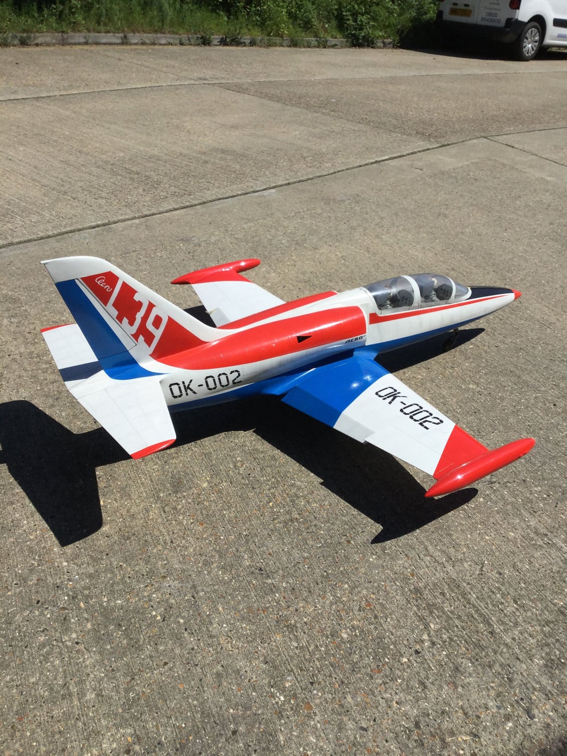
Anyway, weight is just a number. It might just shrug it off, my 20 year old 1/7th Scale AW L-39 weighed 35lb at take off and all my friends said don�t fly it!! I still have it to this day and although landing fast, it flys great. You have a ton more lifting area than that has!
Dave
What what you have done is just amazing, let me state right now I could not produce what you have in your shop...but if I lived down the road and could drop in for a brain storming session, I�m convinced I could help you shave 10lb off the model and it still be tough and strong. We over build our models in so many ways, it�s knowing where you can and cannot reduce material and still achieve strength. DerJet models can be lightened too, I�ve �picked� on Jack too over the years to change the structure and lighten things. My prototype Vampire I emailed him and said I have the tailplane in my hands and thought you had sent me the plug! I could stand on that and it would not break. He reduced glass cloth layers and shifted weight on all future kits...it�s still too strong!
Multiple layers of light cloth, laid the right way in patches for some areas, will give a very rigid structure without the resin weight. Your wood structure could have been lighter and still taken all the loads required, trapped between two skins the I beam nature makes it incredibly strong.
I had a 44� electric model design published 30 years ago for old 7 cell Nicad and brushed 540 motor and the magazine editor was a model designer too, he laughed when I sent in the plan, the total plywood in the whole model was less than 2� Sq of 1/16� 5ply. He said you don�t put anything where it�s not needed do you!
Anyway, weight is just a number. It might just shrug it off, my 20 year old 1/7th Scale AW L-39 weighed 35lb at take off and all my friends said don�t fly it!! I still have it to this day and although landing fast, it flys great. You have a ton more lifting area than that has!
Dave