CARF-Models Mig 17 build thread


The following users liked this post:
kimhey (05-30-2022)
 05-31-2022, 12:48 PM
#102

Thread Starter
Servo arm position for the main gear doors needs to be like this, all the load is when the doors are closed, so the pushrod needs to pass over the servo arm screw. When the door is open in the airflow ( door sits almost vertical) there is almost no G or airflow load.
This is just a geometry check, I�m going to use metal arms.

Closed
Open
This is just a geometry check, I�m going to use metal arms.
Closed
Open
06-03-2022, 10:45 AM
#103
Thread Starter
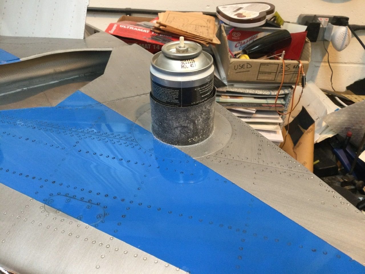
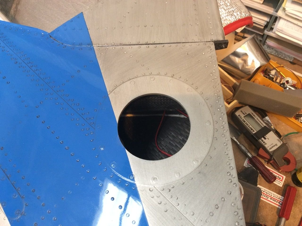
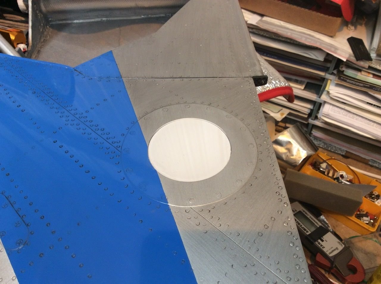
Landing light hole cut and made 100% circular. Laser cut clear lens. Layers of glass paper added to tin, the overhang allows a feed in to start sizing.
I added more layers to get a clearance hole
I added more layers to get a clearance hole
 06-03-2022, 01:00 PM
#105
Thread Starter
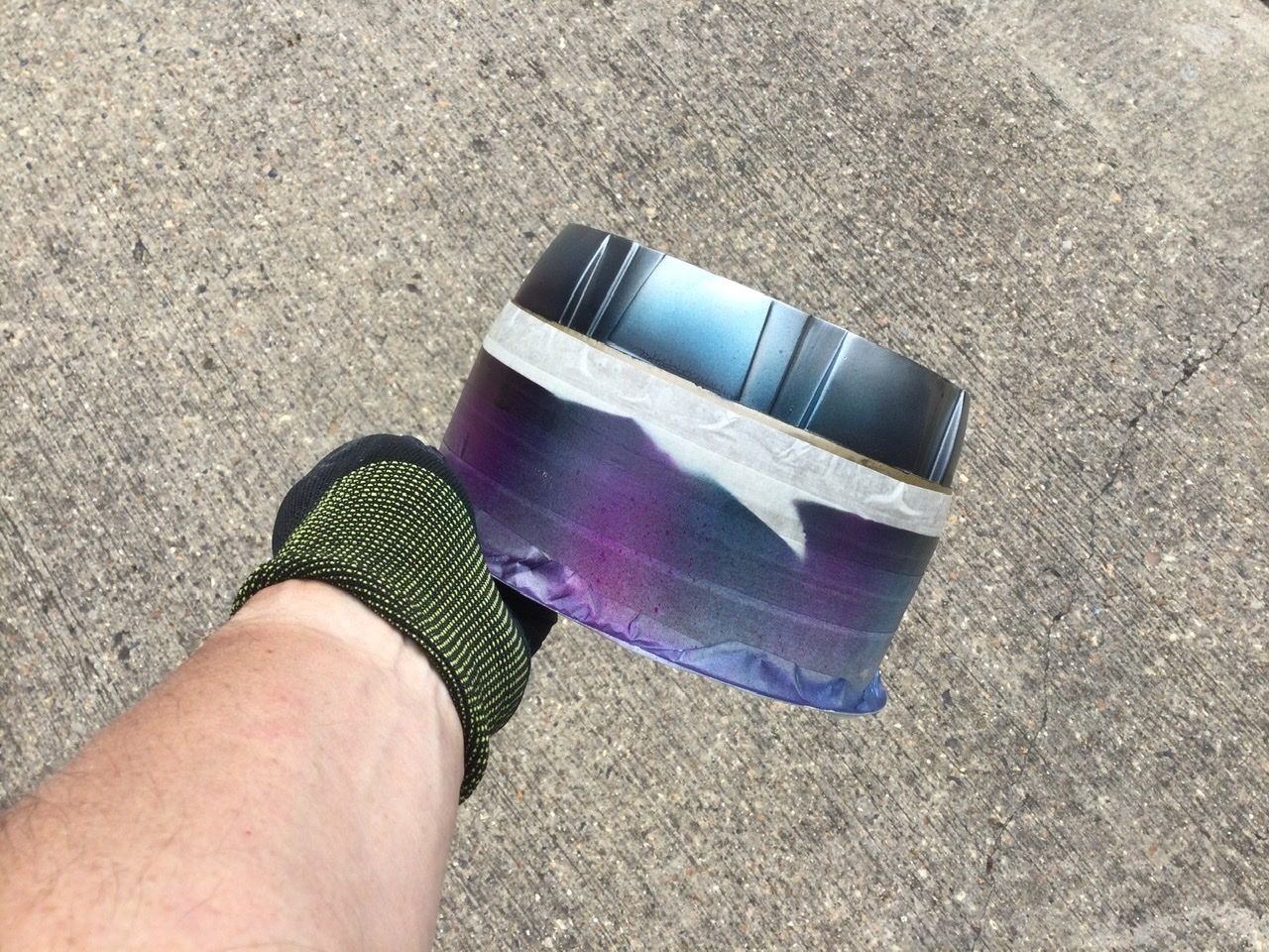
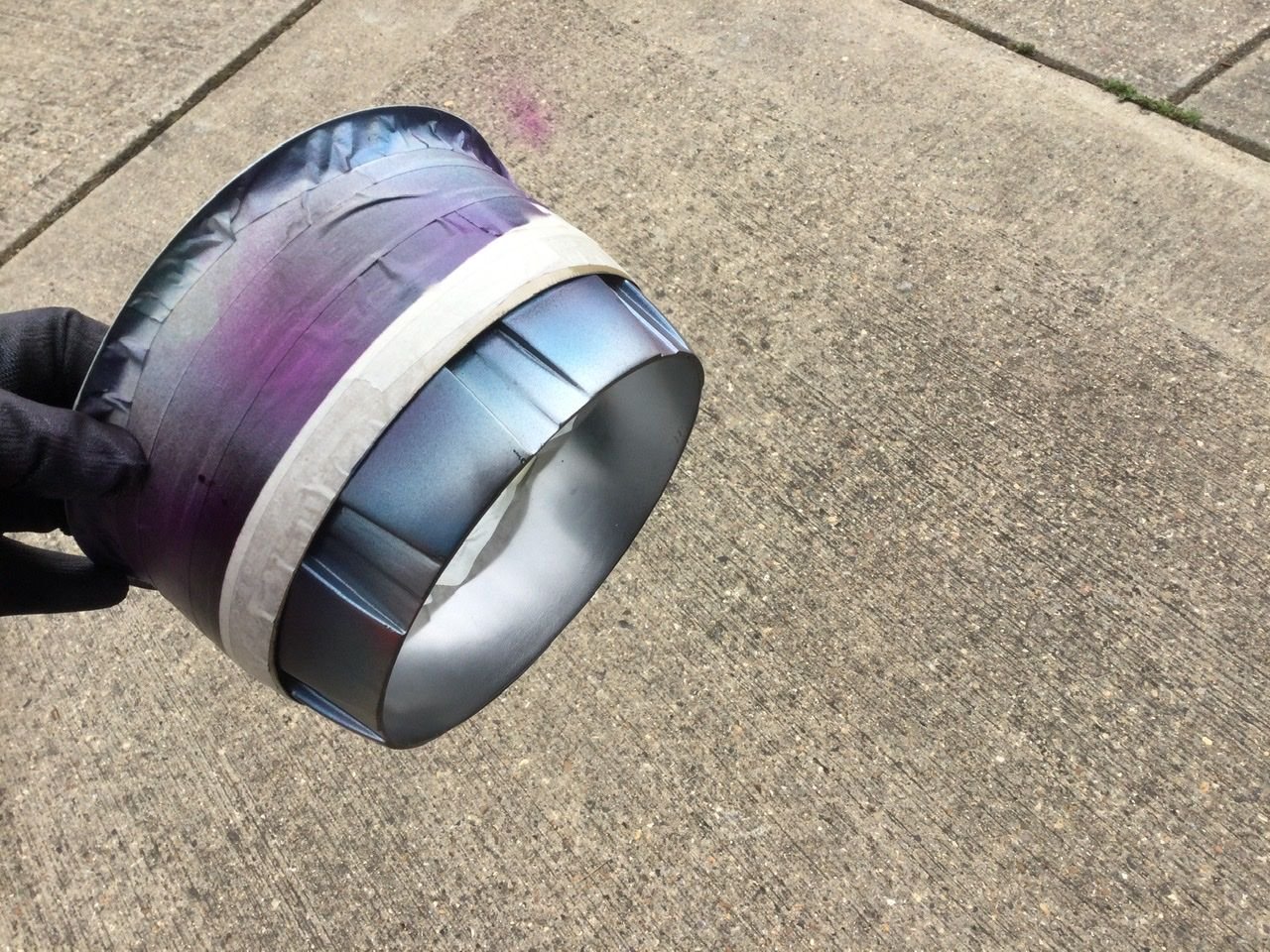
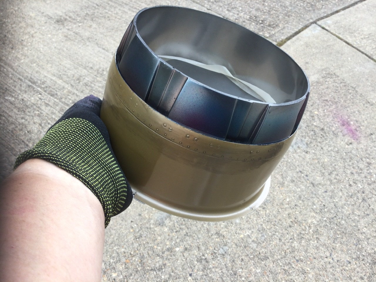
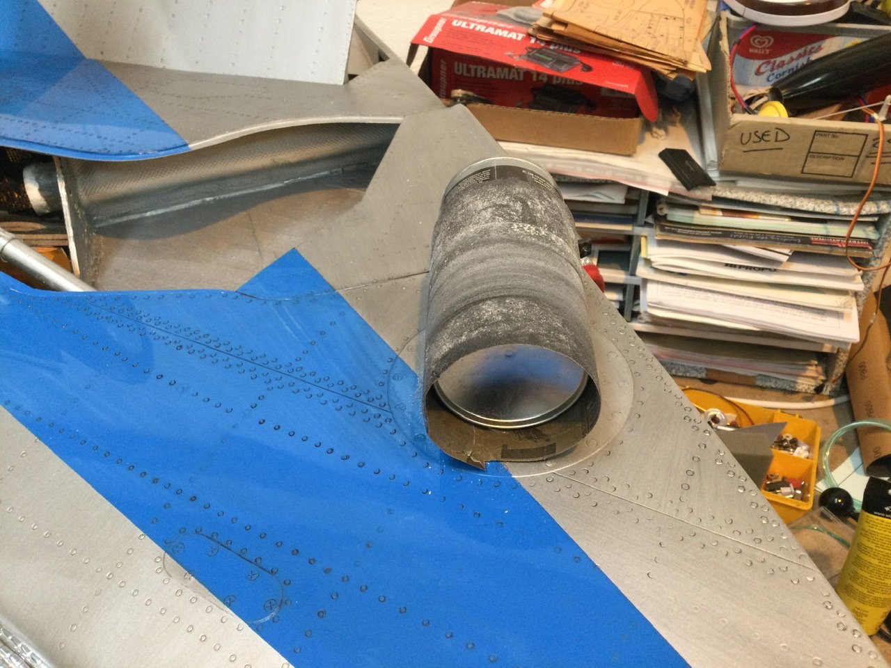
Yes, I got the Unilight set. I noticed looking at the FS early on how prominent the glass lens landing light was…I also decided the 50mm light was too small. That started a stupid idea to increase the diameter and add a clear lens over. It’s been a whole lot of work.
But making the hole is valid what ever the dia.
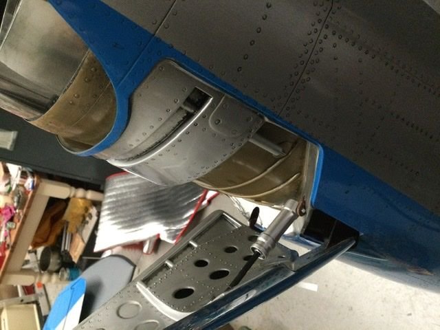
No the dummy cylinders was something I just did along with the after burner pipe work detail I decided to add. The cylinders are CARF items I had spare, they are the ones they supplied after the Robart 165 became too expensive.
But making the hole is valid what ever the dia.
No the dummy cylinders was something I just did along with the after burner pipe work detail I decided to add. The cylinders are CARF items I had spare, they are the ones they supplied after the Robart 165 became too expensive.
06-03-2022, 01:31 PM
#106
Got it, thanks Dave. I'm working on the lighting system in the wings and tail right now. I agree this is a lot of work for some reason. Also, my Black.4 servo lead to the receiver broke at the board only after handling it a little bit on the bench. I contacted uniLight via there website about it and Ulrich got back to me right away about how to take it apart and solder the wires. Looking at the way they soldered the wires to the board they didn't tin or include flux on the ends of the wires. I redid each one under magnification reassembled it and the unit is working fine so far. Very impressed with the help from uniLight on this.
 06-04-2022, 01:01 PM
#108
I have finally received all parts of my kit.
All the great things that have been said are spot on !! Spectacular work Andreas.
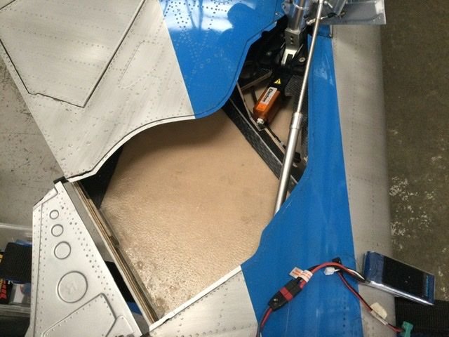
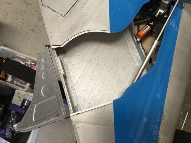
So far the only thing that I have modified is the wing LE section of the fuselage. It is way too soft for my liking .... I tend to grab the fuse by that area when moving it around.
I made an opening at the root and reinforced the inside of the skins with heavy CF, also added a rib at about half way between the root and the fuse (can't work from inside the fuse because the inlet duct is in the way). Feels rock solid now.
Jack
All the great things that have been said are spot on !! Spectacular work Andreas.
So far the only thing that I have modified is the wing LE section of the fuselage. It is way too soft for my liking .... I tend to grab the fuse by that area when moving it around.
I made an opening at the root and reinforced the inside of the skins with heavy CF, also added a rib at about half way between the root and the fuse (can't work from inside the fuse because the inlet duct is in the way). Feels rock solid now.
Jack
The following users liked this post:
kimhey (06-04-2022)
06-04-2022, 03:30 PM
#109
Thread Starter
There might be lots of bits, but they all fitted 😁
06-04-2022, 07:57 PM
#110
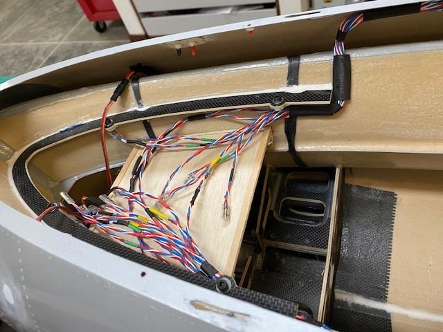
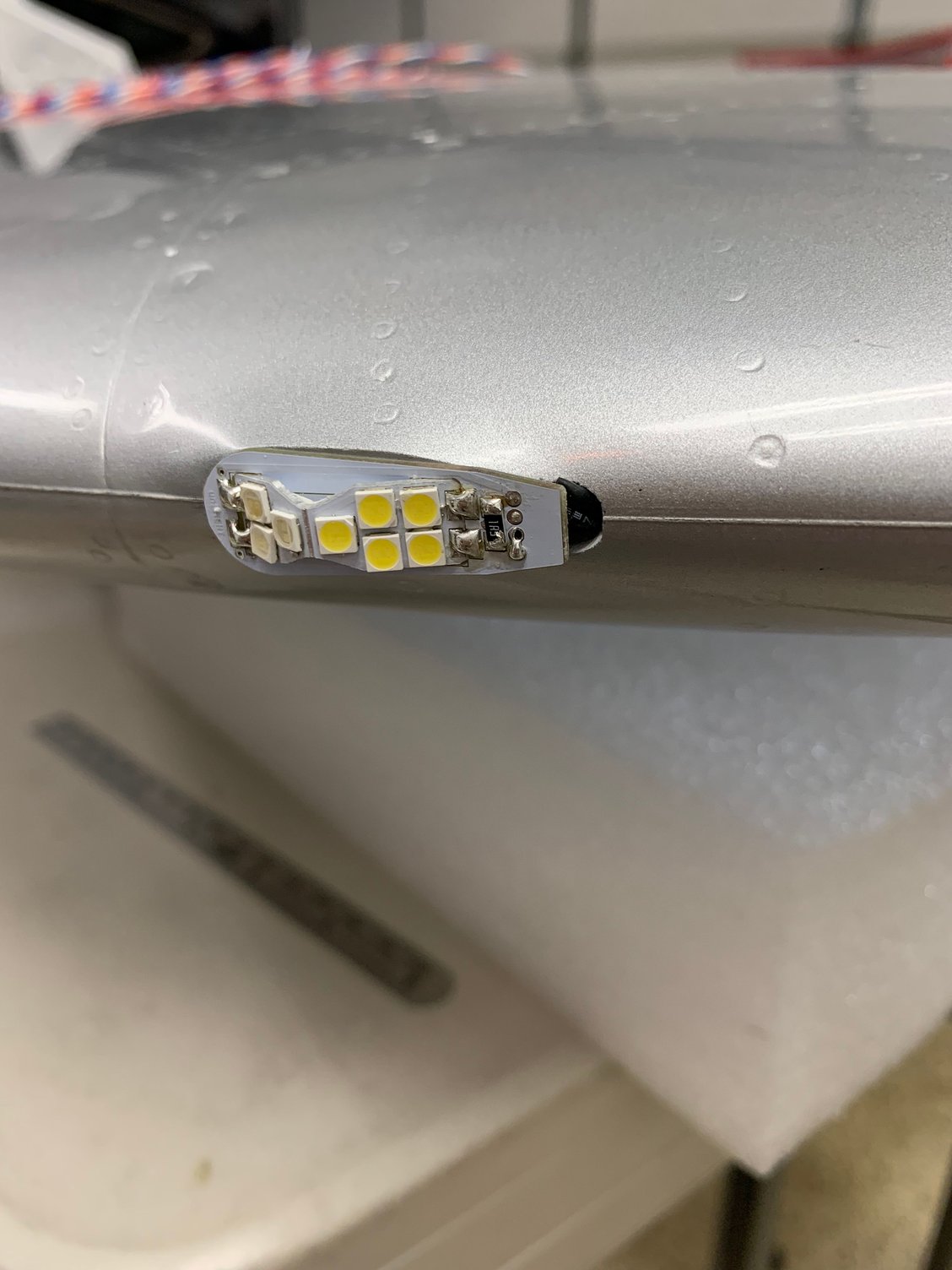
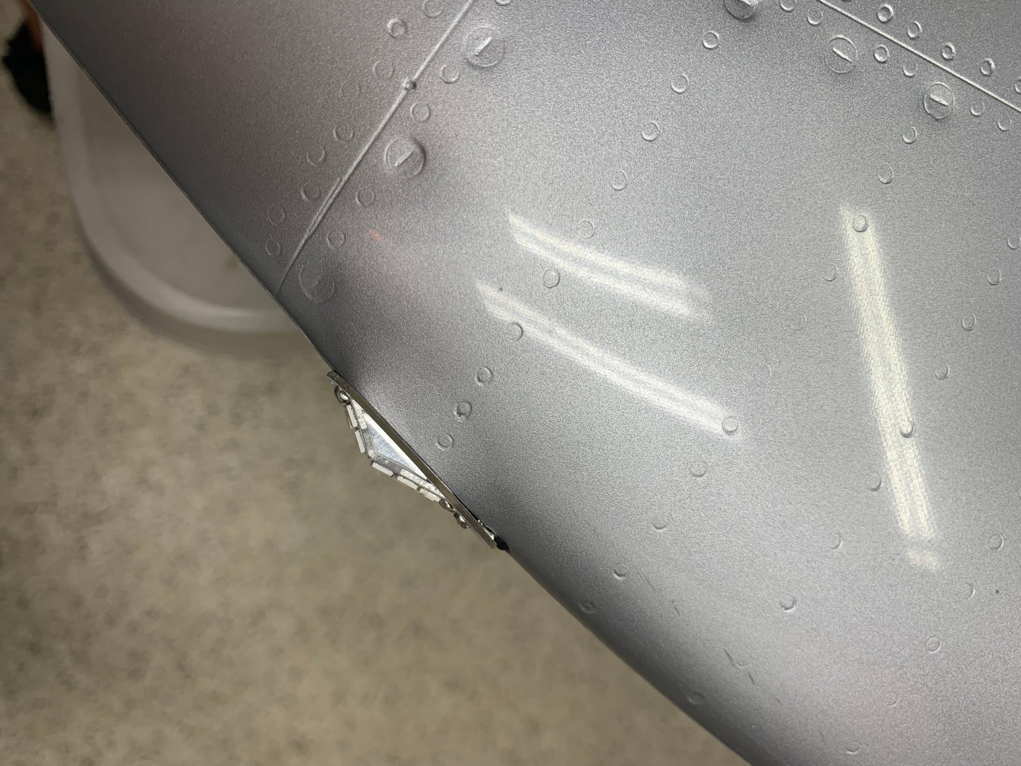
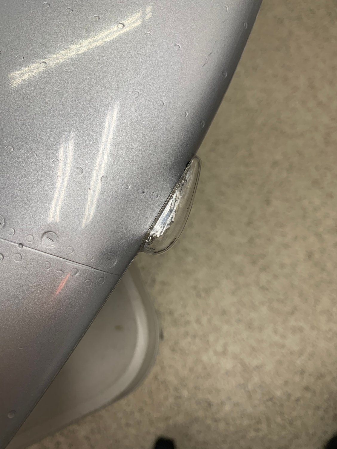
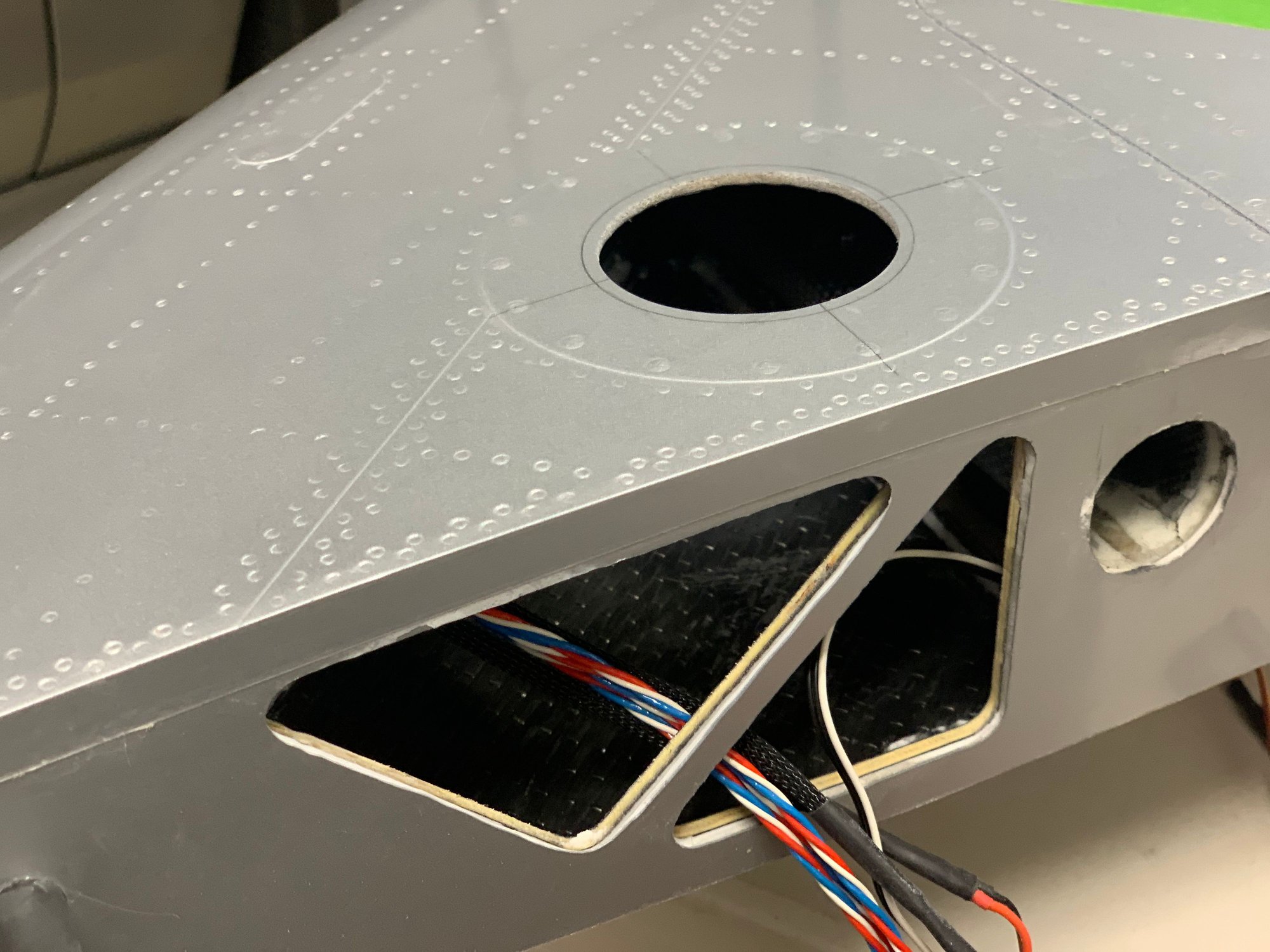
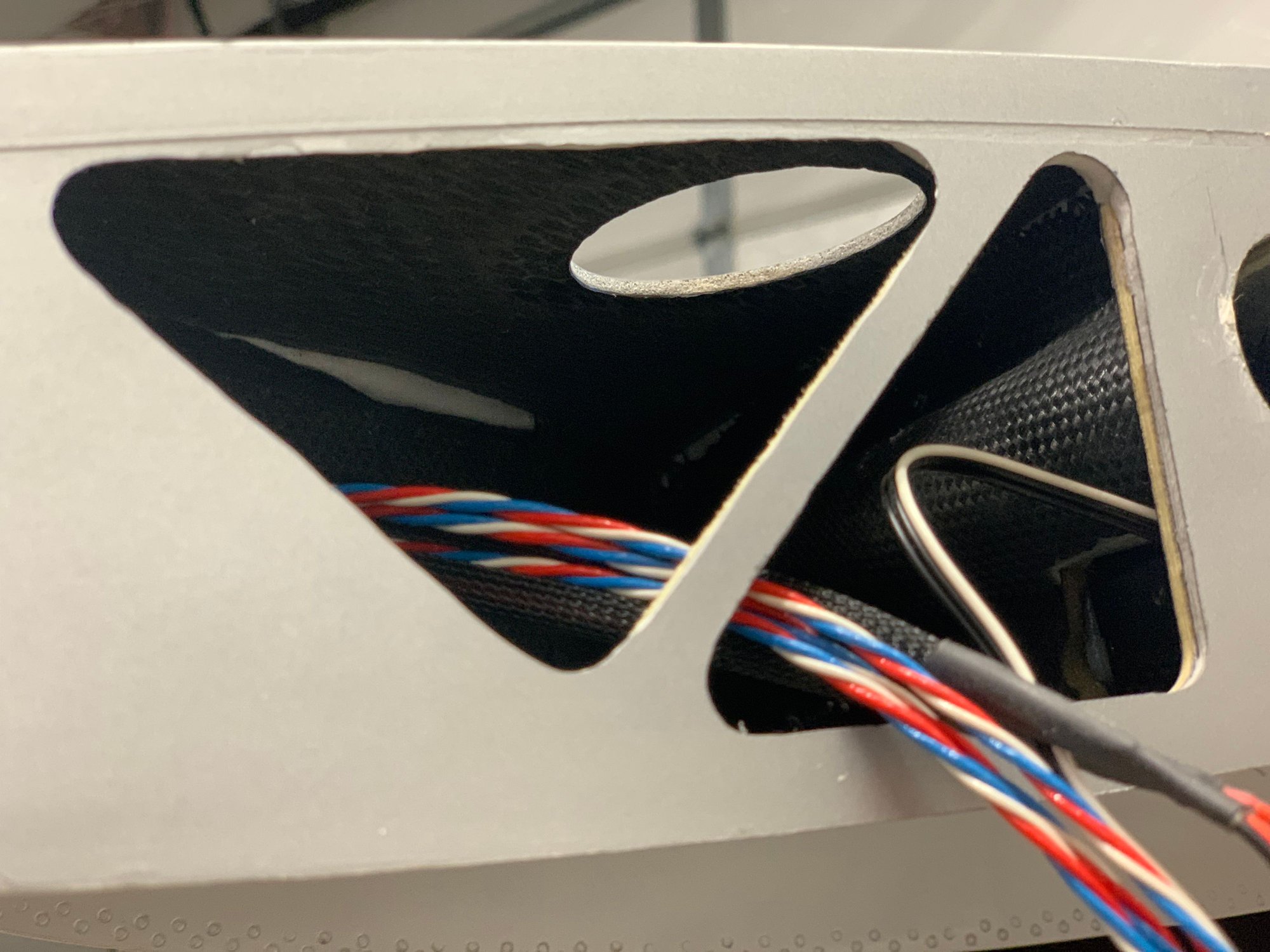
Finished up the wing nav lights and wiring out the wings. It went smoothly however I had to make some minor modifications to the uniLight cooling fins. After slotting the wing tips with a Dremel and file, I test fit the lights and found they didn�t go all the way in. Something inside the wing was blocking them, and additional 4-5mm was needed. Looking through the slots with a flashlight, I could see the issue. I also used a small file to check the structure. There appears to be carbon fiber ribs at some angle preventing them lights from going completely in. I ended up cutting away a few millimeters off the end of the cooling fins. After that they went in fine. Used a small amount of epoxy to glue them in as well as the clear covers. I secured the wiring with tie wraps inside the wing. I did have to extended the wires from the lights out the wing with some PowerBox wire. I will reuse the short portion with the uniLight connectors I cut off inside the fuse. I will need to make a wire harness out of it in order to connect everything up from the wings and tail.

Slot and modified nav light
Nav light
Nav light
Nav light
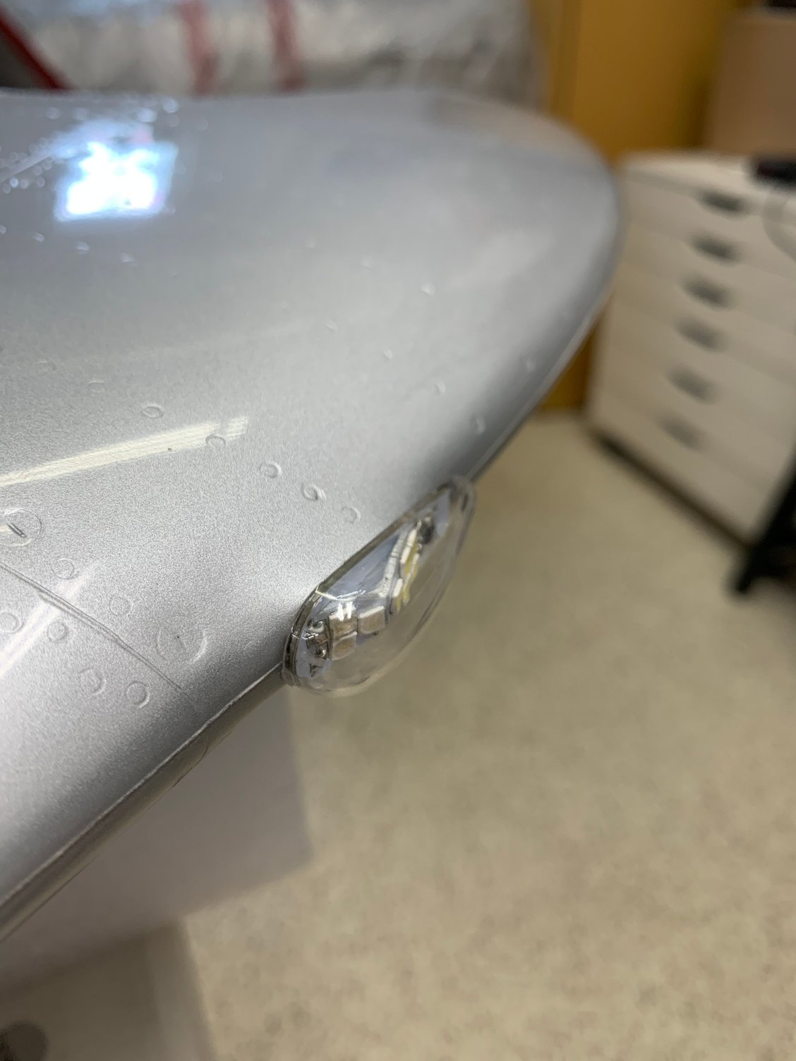
Attached nav light
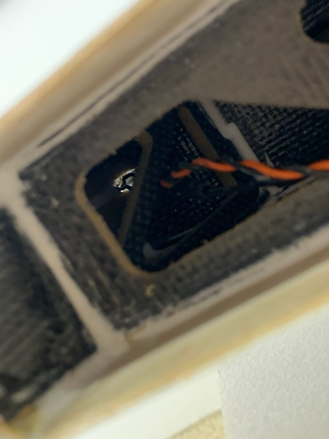
Inside view (via aileron location) of attached nav light
Slot and modified nav light
Nav light
Nav light
Nav light
Attached nav light
Inside view (via aileron location) of attached nav light
 06-05-2022, 10:17 AM
#112
Thread Starter
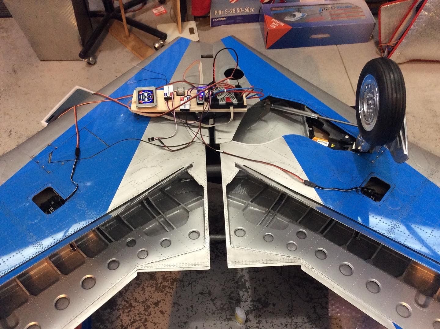
Flaps matched. Wings joined with spars, first wing completed with my desired flap angles. Second wing matched to first. I don�t measure deflection preferring to eye standing on the centre line.
Full flap has pushrods inline with servo horn at full flap to reduce load.
As always with my builds the PB, Rx�s, batteries, switch etc are all for the model-so by the time of the first flight there will be 50+ cycles through the system

Full flap has pushrods inline with servo horn at full flap to reduce load.
As always with my builds the PB, Rx�s, batteries, switch etc are all for the model-so by the time of the first flight there will be 50+ cycles through the system
06-09-2022, 09:50 PM
#113
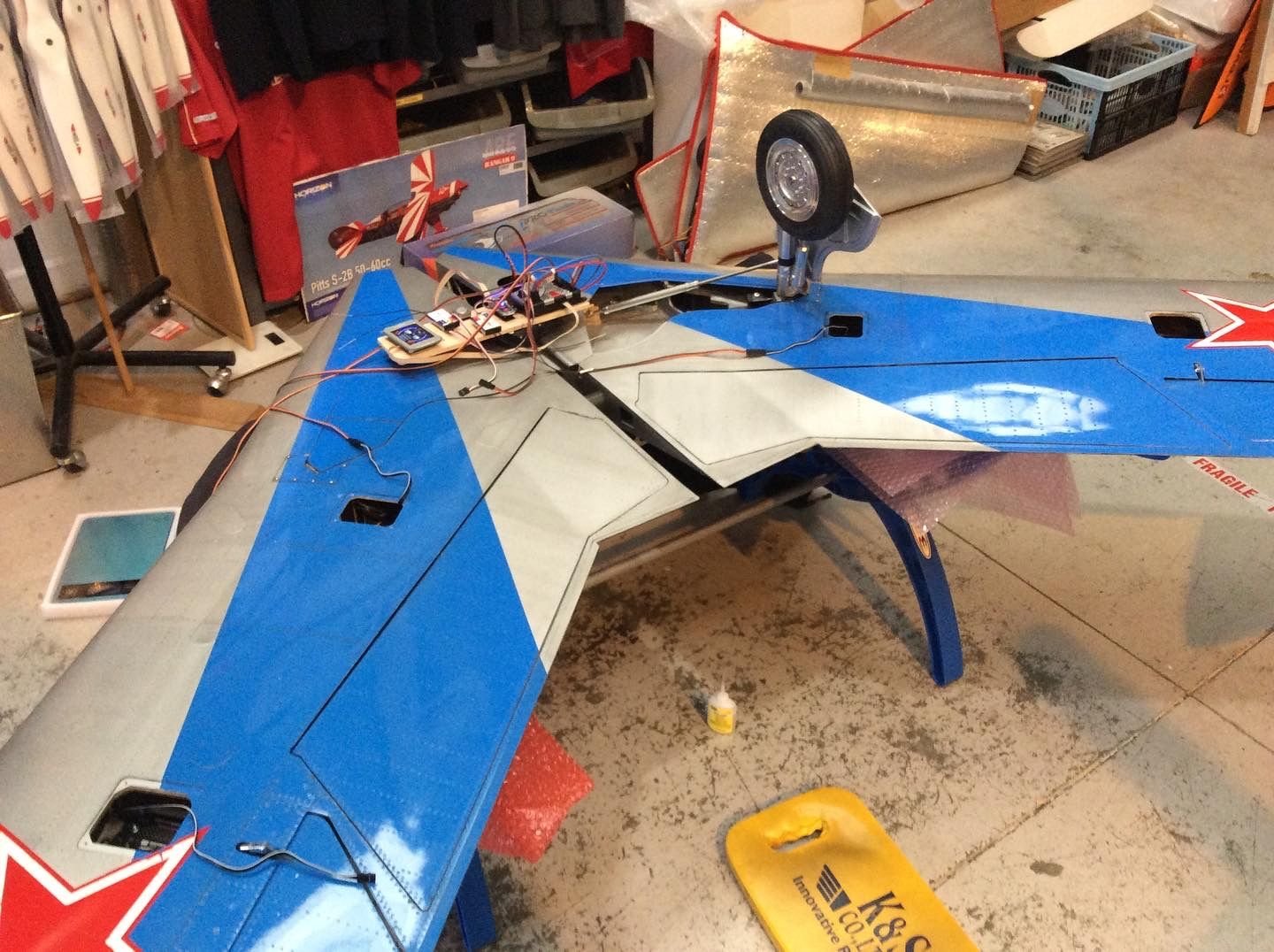
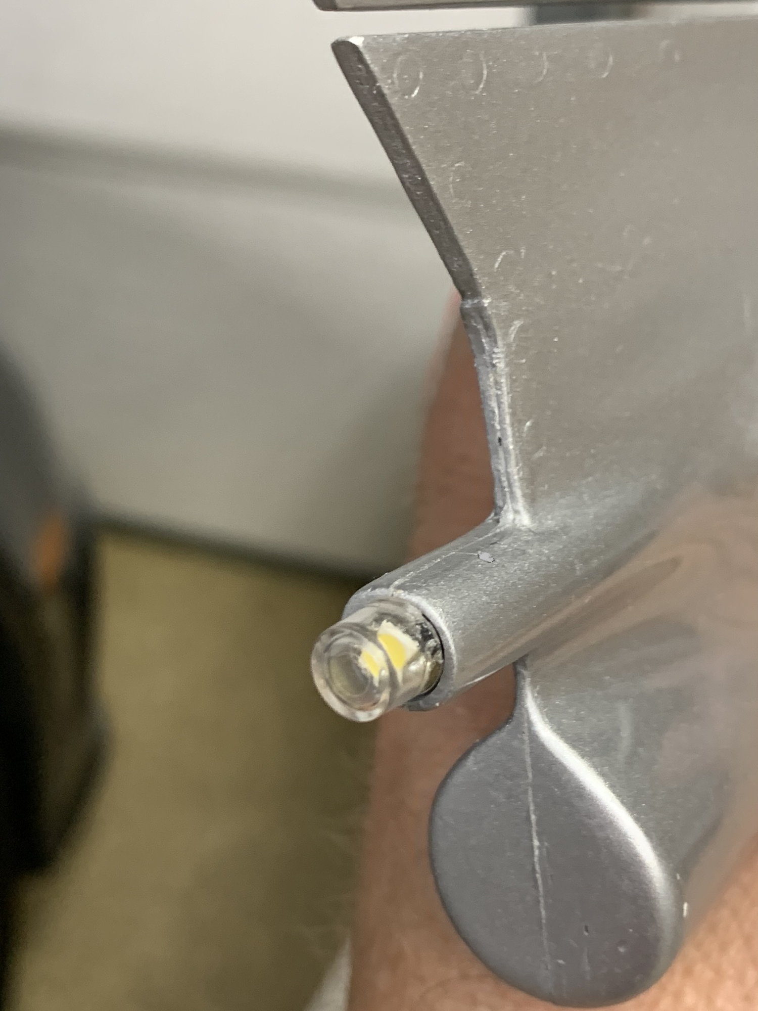
Managed to get the nav light installed in the tail. After some sanding I realized it wasn�t going to fit. In order to save as much material as possible surrounding the nav light assembly I had to file grooves in the aluminum to accommodate the red and black wires. Worked out perfectly. Also I used an extension rod with a drill bit on the end in order to drill a pass through hole into the fin. This will allow the wires to make it inside the fin and on to the exit at the fuselage for connection. Lastly I drilled the pass through holes on either side of the fin for the elevator servo leads. I did run into some wood and hysol in that area so be careful when you make the openings.

Nav light assembly with grooves
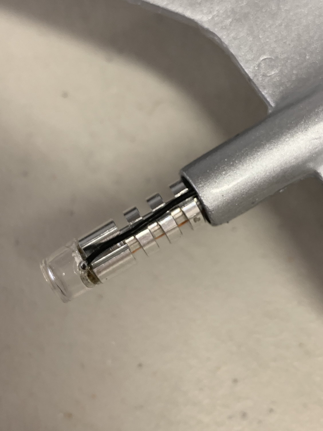
Nav light with tucked wires
Nav light fully inserted
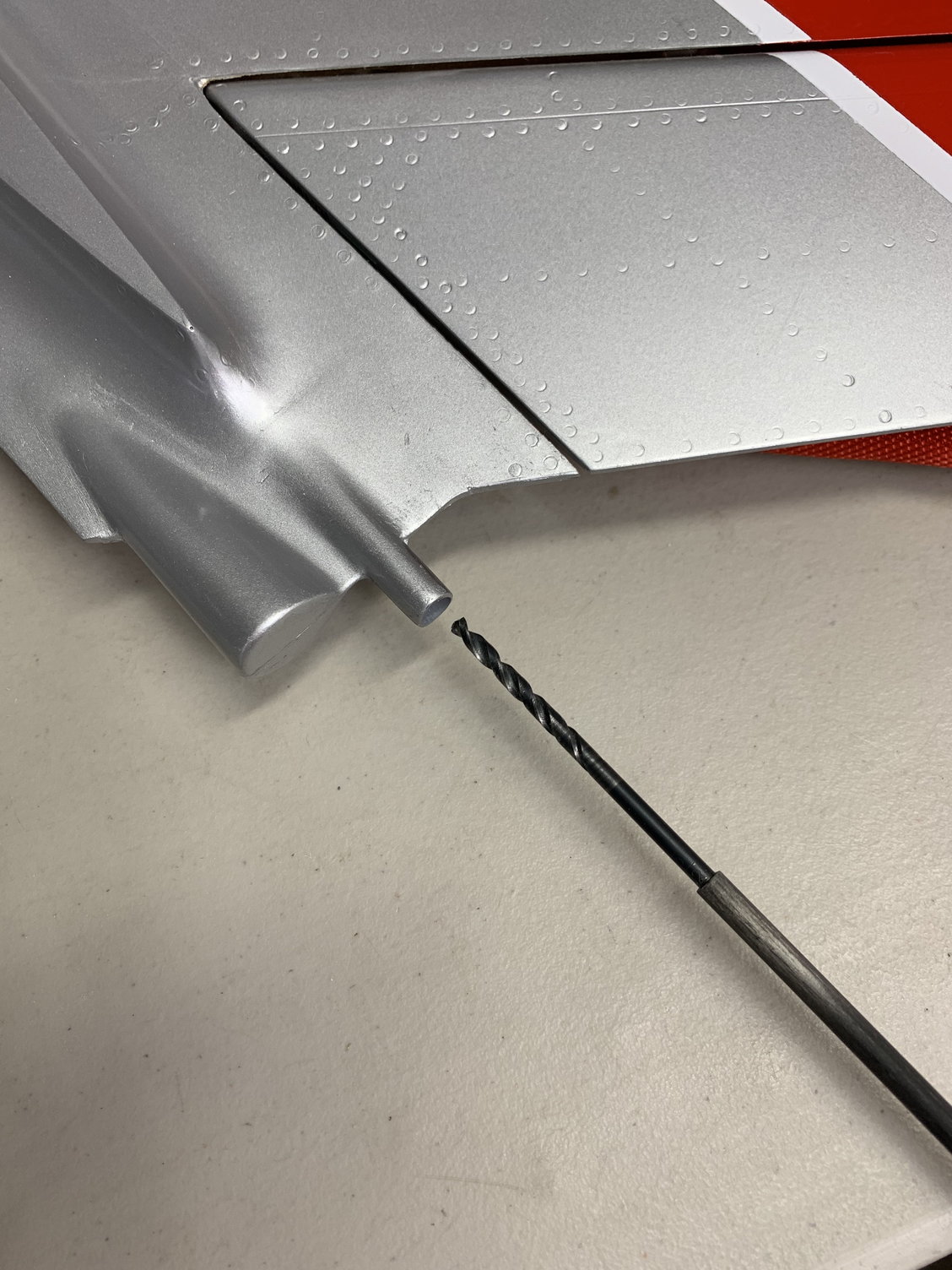
Extension rod with drill bit
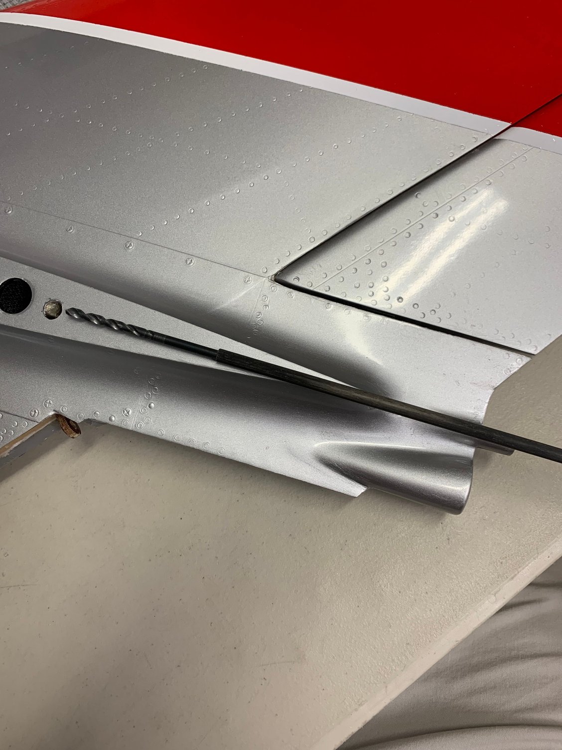
Extension rod with drill bit showing required depth

Elevator servo lead hole
Nav light assembly with grooves
Nav light with tucked wires
Nav light fully inserted
Extension rod with drill bit
Extension rod with drill bit showing required depth
Elevator servo lead hole
06-11-2022, 07:08 PM
#114
I came across a good suggestion by one of the contributors in the CARF Rebel thread the other day and decided to update my control surface linkages with his advice. CARF provides a pin and c-clip for connecting the linkage to the control surface horn. It�s very nice , but apparently the c-clip can be easily removed with a small amount of force especially if it snags on something like a wing bag. So I changed it to a M3 button head screw and nyloc nut.
Updated aileron linkage
Updated aileron linkage
The following users liked this post:
kimhey (06-11-2022)
06-11-2022, 07:33 PM
#115
Finished up the tail nav light and servo leads for the elevators and then moved on to the landing light install today.
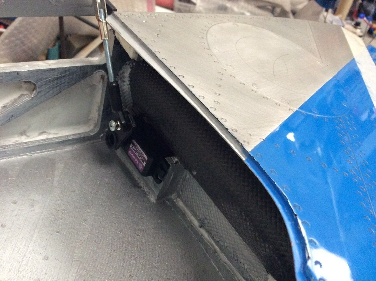
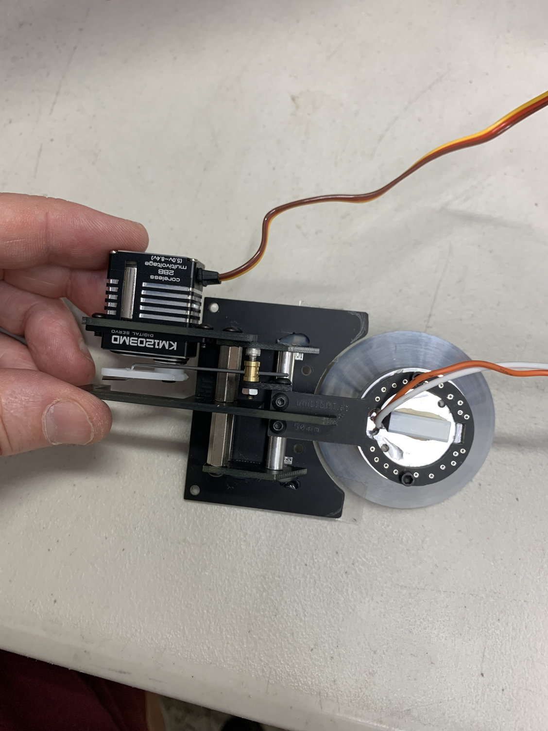
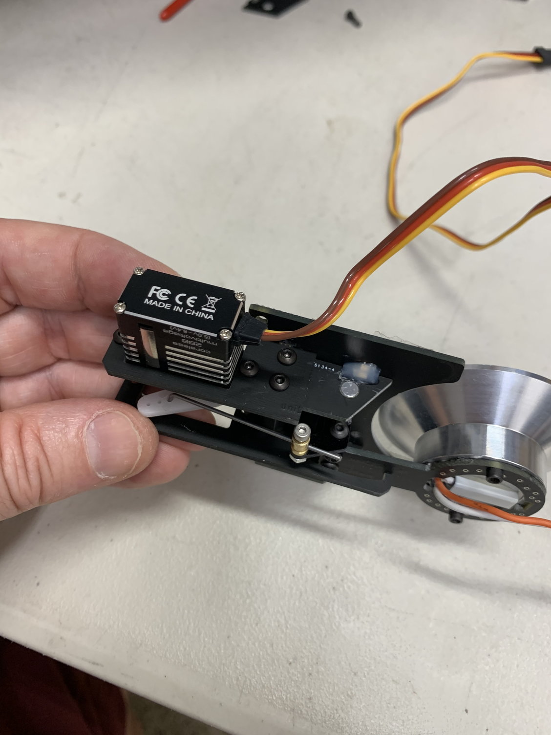
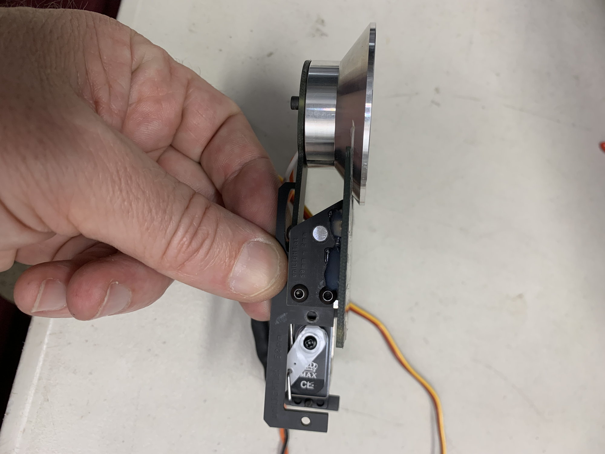
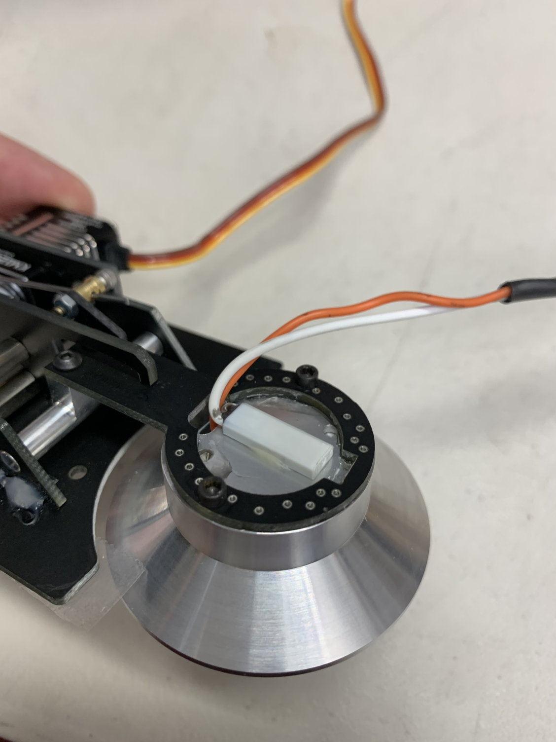
I opened up the uniLight landing light packaging and began looking over the parts. It�s very nice however I noticed right away it needed some adjustments. The servo was pre installed but it was facing the wrong way. Disassembled it from the frame and then reinstalled it correctly. Attached the servo arm and the linkage and did some bench tests with my radio. All looked good.
Next I cut into the wing to get better access to install the light assembly as well as cut the opening for the light to deploy out from. Did a quick fit check and noted some things I may need to do before glueing it in permanently. During the fit check the landing light became unglued from the frame. I�m not sure what kind of glue they used but it seemed inadequate. Something like this should be screwed down as it deploys into the airstream. I�ll look at this a bit more this coming week.
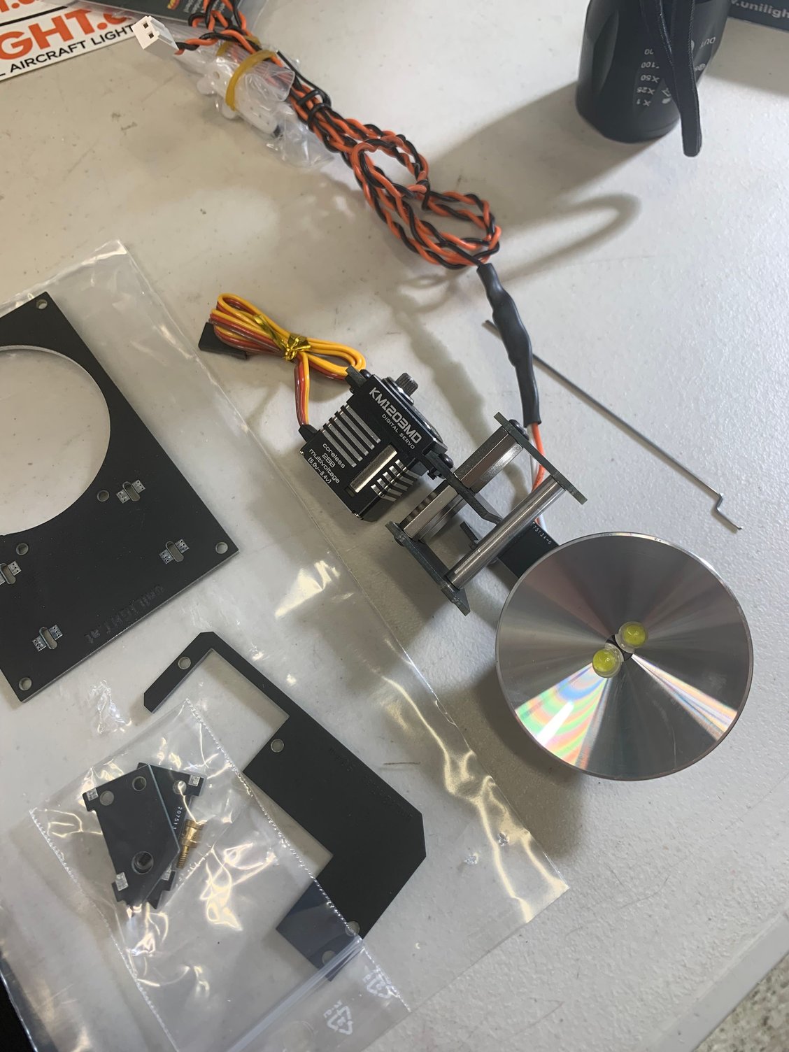
Landing light assembly top view
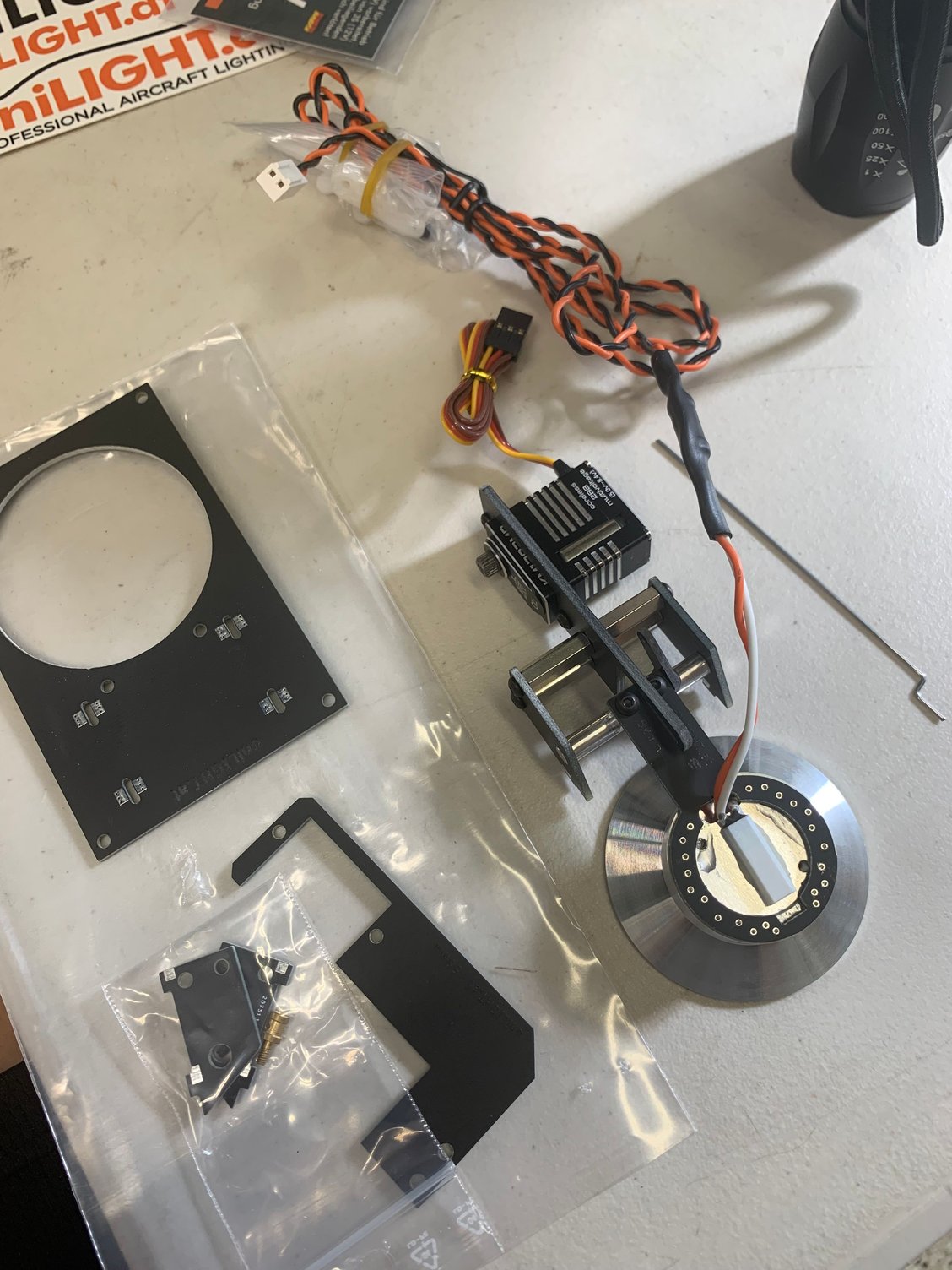
Landing light bottom view after opening packaging

Surface marks prior to drilling out
Dremel openings in wing
View through new opening to help with install
Landing light assembly with opening in wing
Alternate view of the landing light assembly
Test fit of the landing light

Deployed landing light test fit
Landing light test fit front view
Delaminated landing light
I opened up the uniLight landing light packaging and began looking over the parts. It�s very nice however I noticed right away it needed some adjustments. The servo was pre installed but it was facing the wrong way. Disassembled it from the frame and then reinstalled it correctly. Attached the servo arm and the linkage and did some bench tests with my radio. All looked good.
Next I cut into the wing to get better access to install the light assembly as well as cut the opening for the light to deploy out from. Did a quick fit check and noted some things I may need to do before glueing it in permanently. During the fit check the landing light became unglued from the frame. I�m not sure what kind of glue they used but it seemed inadequate. Something like this should be screwed down as it deploys into the airstream. I�ll look at this a bit more this coming week.
Landing light assembly top view
Landing light bottom view after opening packaging
Surface marks prior to drilling out
Dremel openings in wing
View through new opening to help with install
Landing light assembly with opening in wing
Alternate view of the landing light assembly
Test fit of the landing light
Deployed landing light test fit
Landing light test fit front view
Delaminated landing light
06-11-2022, 09:50 PM
#116
Thread Starter
I came across a good suggestion by one of the contributors in the CARF Rebel thread the other day and decided to update my control surface linkages with his advice. CARF provides a pin and c-clip for connecting the linkage to the control surface horn. It�s very nice , but apparently the c-clip can be easily removed with a small amount of force especially if it snags on something like a wing bag. So I changed it to a M3 button head screw and nyloc nut.
Updated aileron linkage
Updated aileron linkage
it�s only valid if you can find a bolt with smooth section to use.
My model will have the supplied pins and clips�
The following users liked this post:
paulhat (06-13-2022)
06-12-2022, 10:50 AM
#117
I came across a good suggestion by one of the contributors in the CARF Rebel thread the other day and decided to update my control surface linkages with his advice. CARF provides a pin and c-clip for connecting the linkage to the control surface horn. It�s very nice , but apparently the c-clip can be easily removed with a small amount of force especially if it snags on something like a wing bag. So I changed it to a M3 button head screw and nyloc nut.
Updated aileron linkage
Updated aileron linkage
I have hundreds of flights on my CARF fleet, including vibrating planes like P-47 or Corsair, with 250's Moki.
They use the pin and clip system you mentioned. I have never had a problem with them.
Advise: beware of experts ..... they are extremely dangerous

Jack
The following users liked this post:
Dave Wilshere (06-12-2022)
 06-12-2022, 03:12 PM
#119
Dave, Jack,
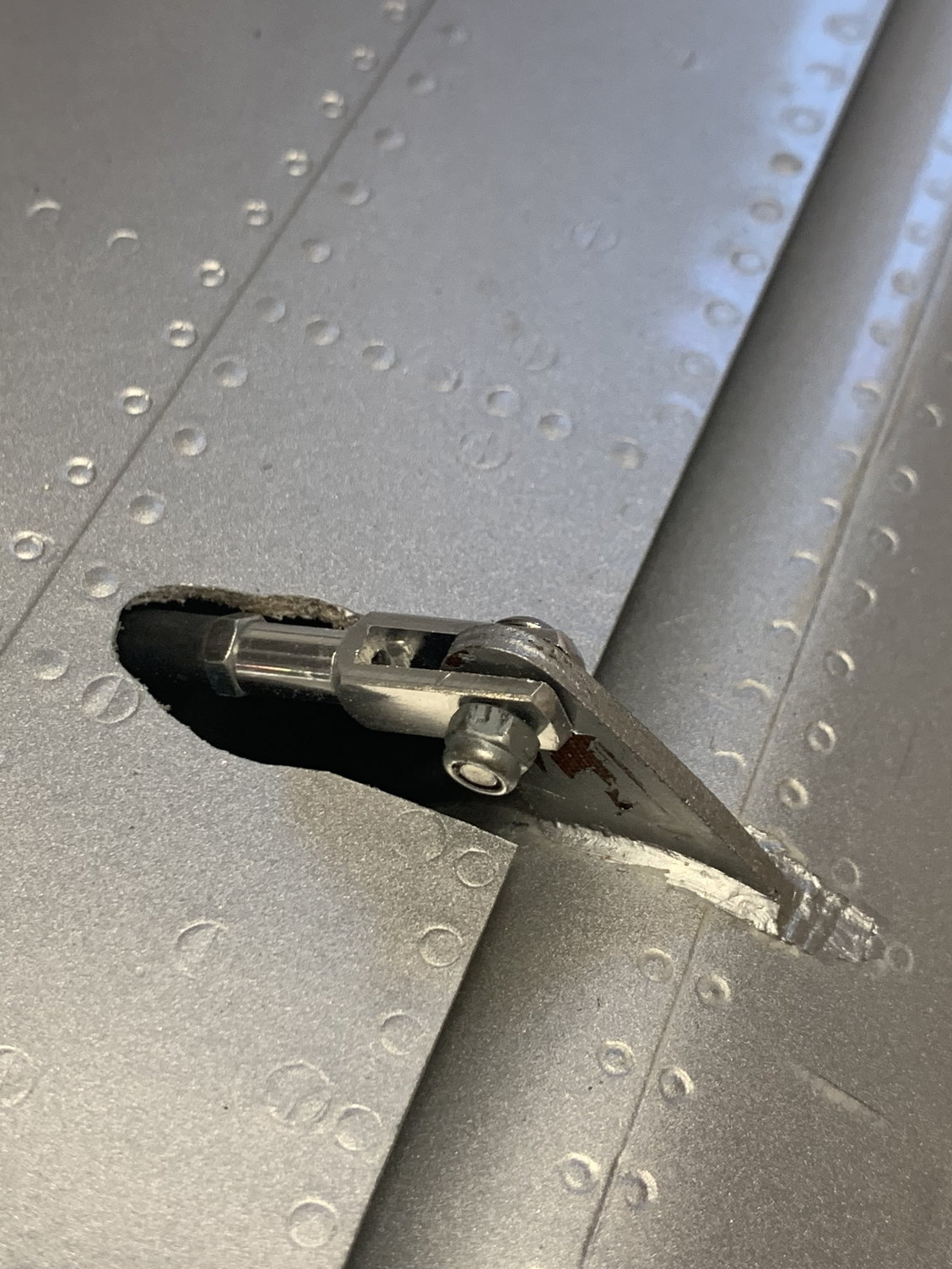
Thanks for the feedback on using M3 threaded screws verses the CARF pins. I think it�s probably OK to use them as you pointed out, but I ended up sourcing some M3 shoulder screws cut to size. Used some thread locker as well to finish assembling the control linkage. Picture below.
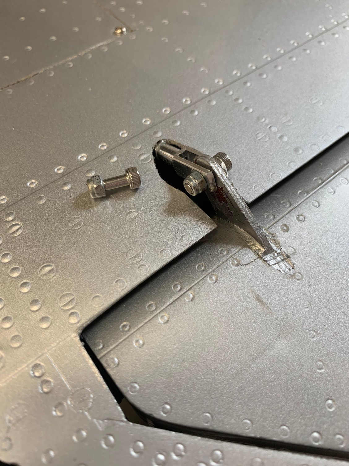
M3 shoulder screw cut to length
Thanks for the feedback on using M3 threaded screws verses the CARF pins. I think it�s probably OK to use them as you pointed out, but I ended up sourcing some M3 shoulder screws cut to size. Used some thread locker as well to finish assembling the control linkage. Picture below.
M3 shoulder screw cut to length
The following users liked this post:
jackdiazccs (06-12-2022)
06-12-2022, 10:35 PM
#121
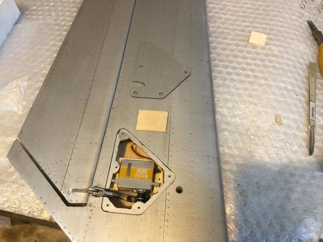
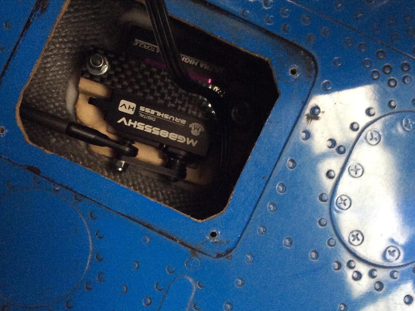
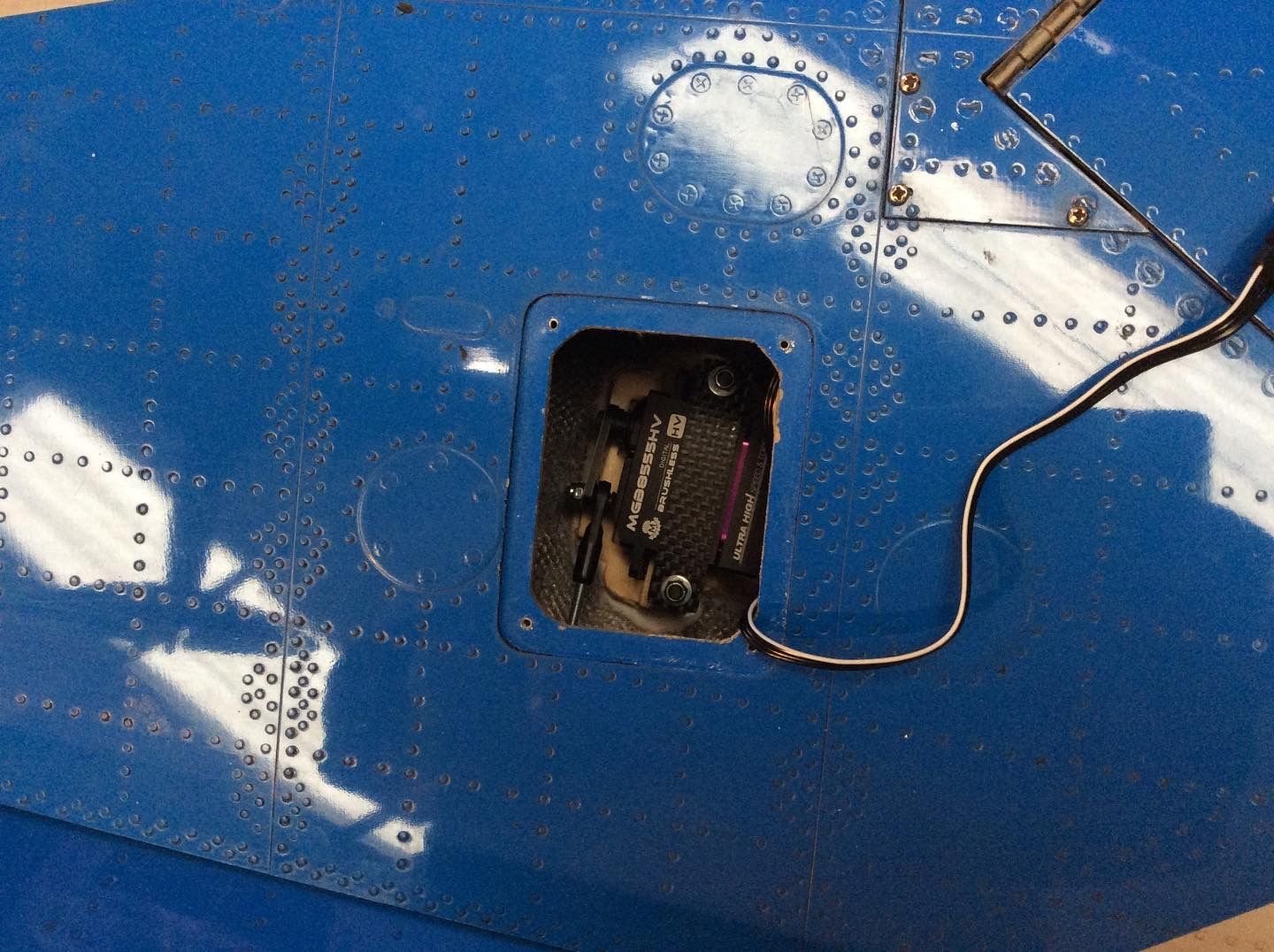
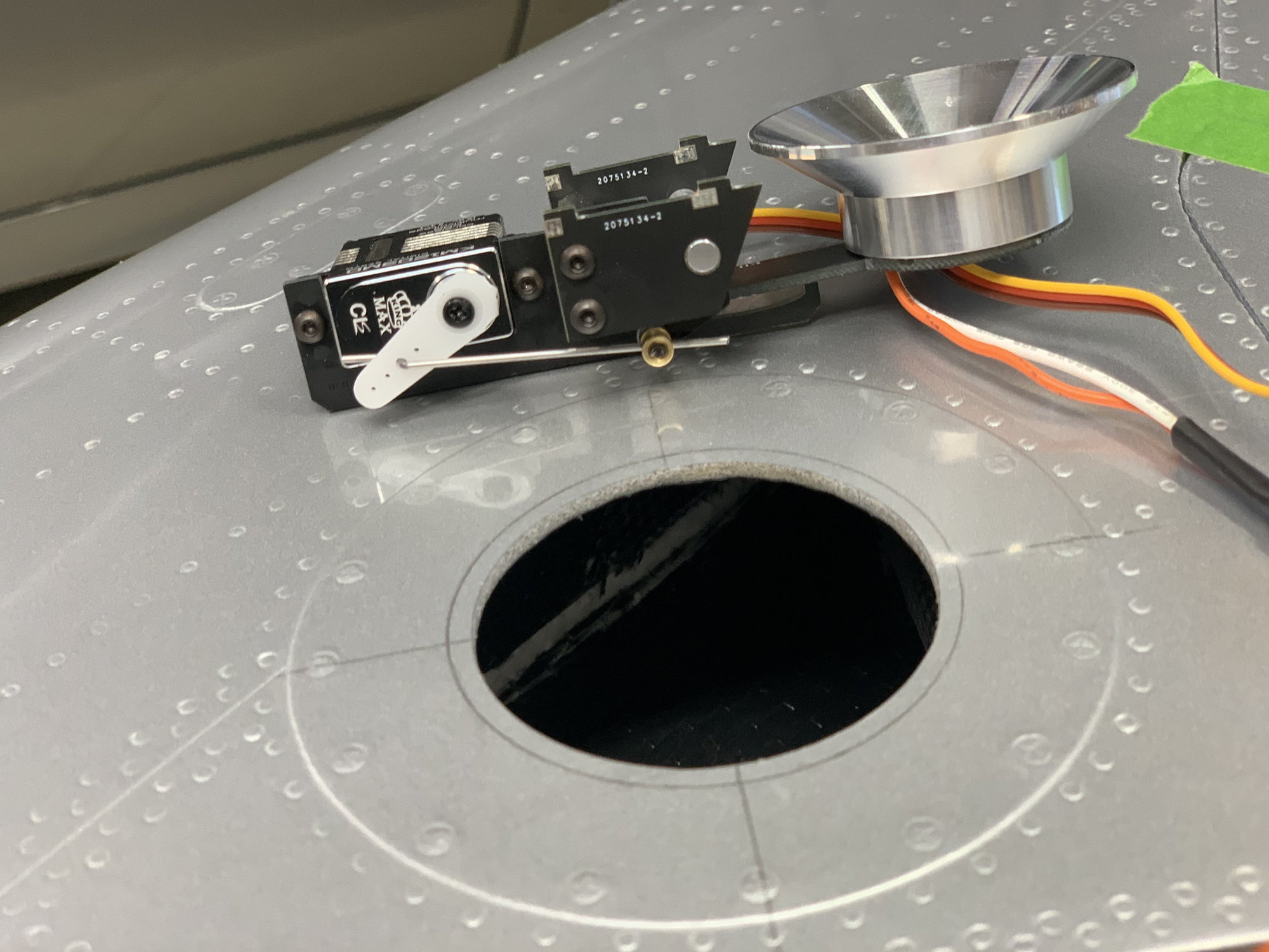
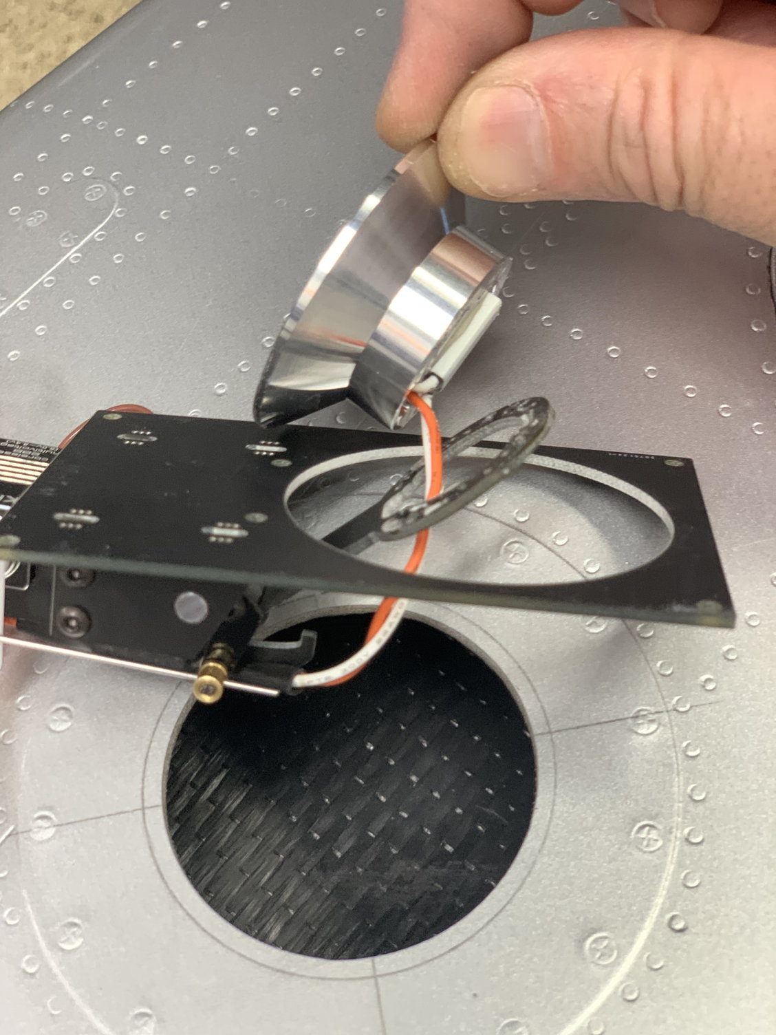
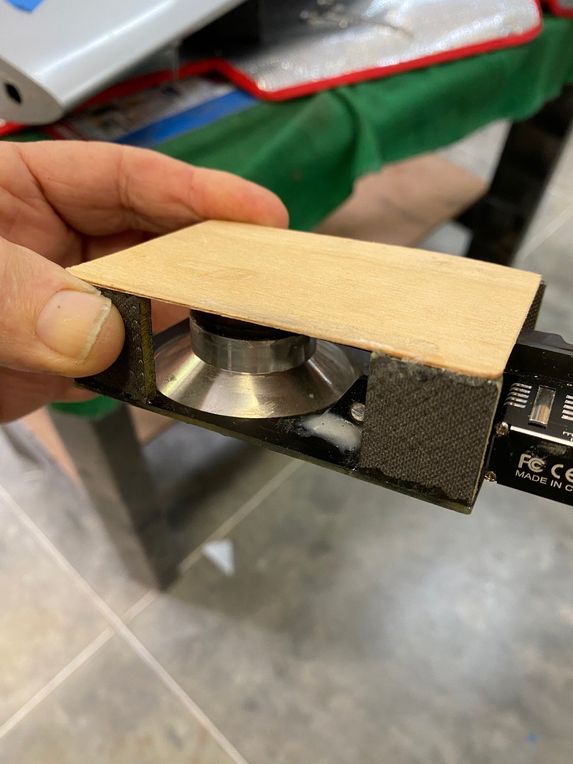
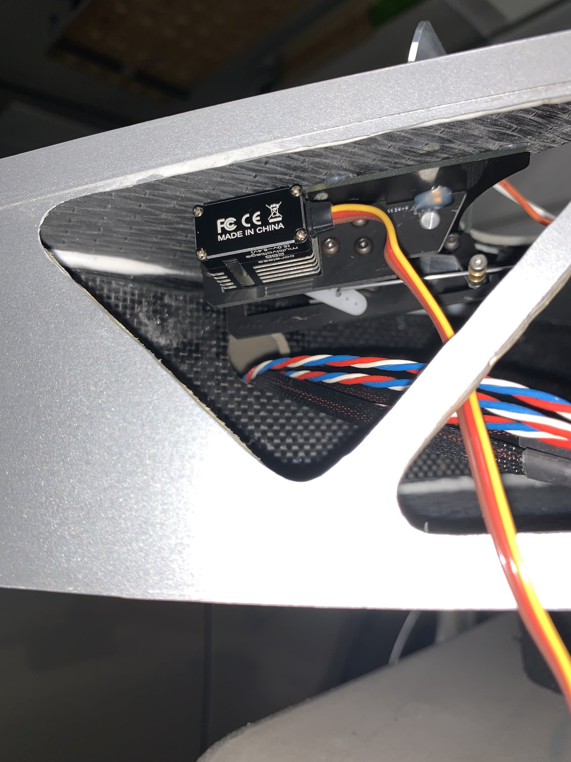
Worked on the landing light a bit more today and decided to redesign the servo mounting. I had originally set it up the way CARF had shown in some pictures I received. When I went to test fit it inside the wing again I noticed that the light was not centering correctly which would cause it to deploy more towards the fuselage.
Turns out the back corner of the servo was hitting the main support structure near the hole where the servo leads exit. I studied the CARF photos more closely and saw that they hacked away some material in that area to allow the servo to move further into the wing. We�ll I didn�t want to do that and opted for mods on the light assembly.
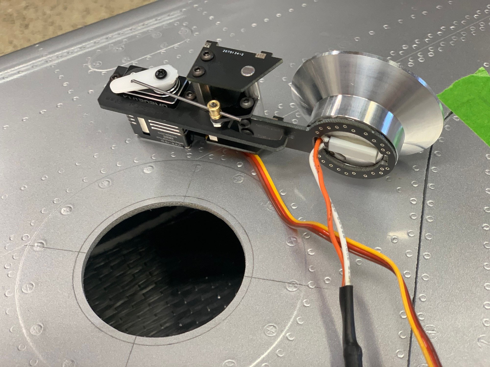
All the mods still allow for servicing and especially the LED light, I drilled two holes and tapped them for 2-56 socked heads screws in case I need to take it out for any reason.
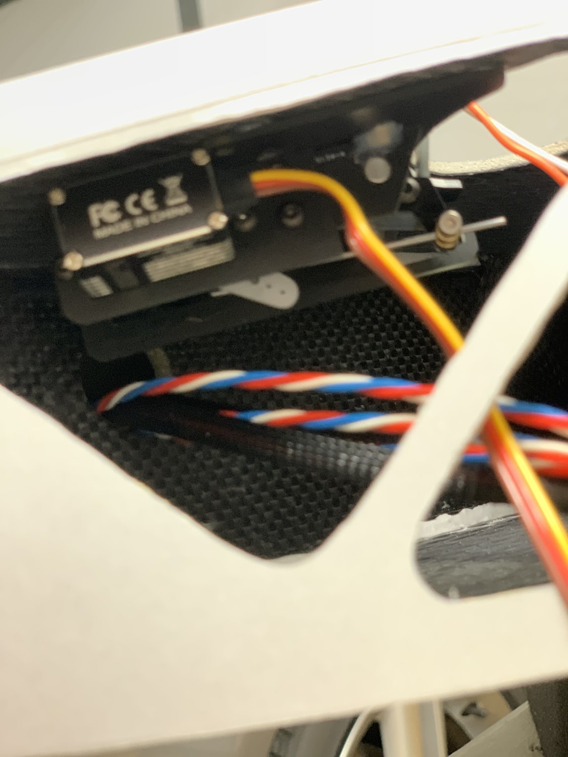
Finally, I put a couple of dabs of hot glue on the mounting plate and installed it in the wing to do some testing before permanently gluing the entire assembly. I took a short video and some pictures. Any comments on this are welcome.
Light assembly bottom view
View of the landing light mods
Another view of the landing light mods
Landing light mounted with screws
Landing light retracted
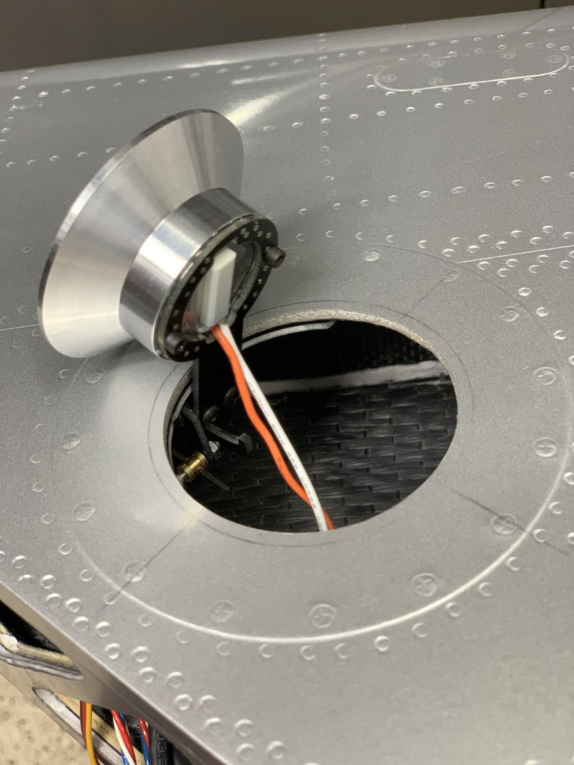
Landing light deployed
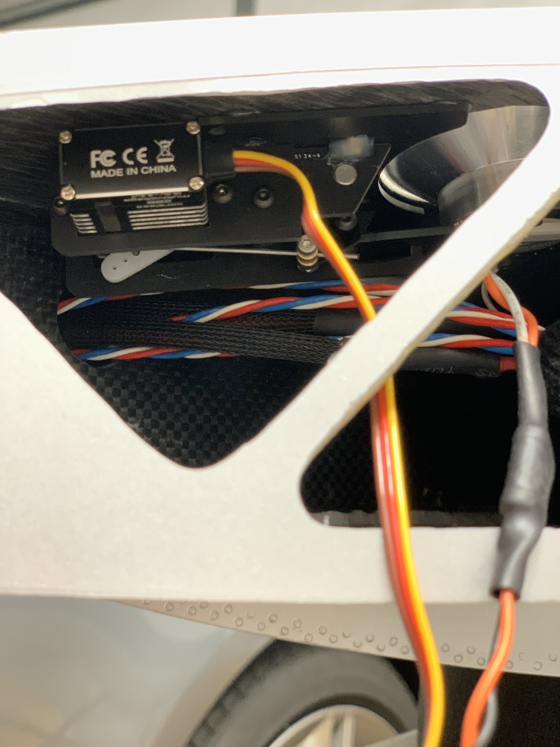
Light assembly in the wing
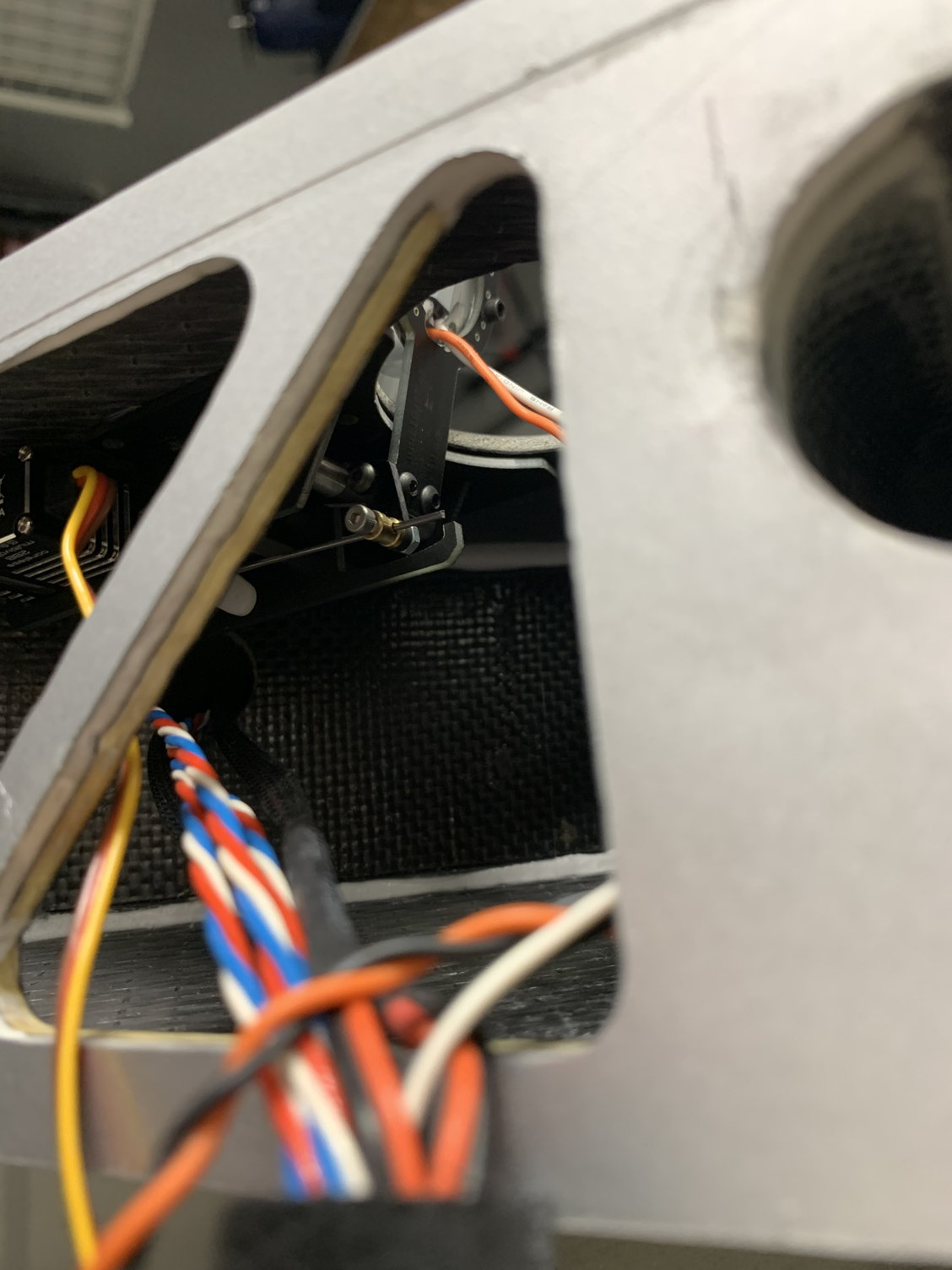
View inside wing towards light
View inside wing toward servo
Another view of the landing light in the wing
Turns out the back corner of the servo was hitting the main support structure near the hole where the servo leads exit. I studied the CARF photos more closely and saw that they hacked away some material in that area to allow the servo to move further into the wing. We�ll I didn�t want to do that and opted for mods on the light assembly.
All the mods still allow for servicing and especially the LED light, I drilled two holes and tapped them for 2-56 socked heads screws in case I need to take it out for any reason.
Finally, I put a couple of dabs of hot glue on the mounting plate and installed it in the wing to do some testing before permanently gluing the entire assembly. I took a short video and some pictures. Any comments on this are welcome.
Light assembly bottom view
View of the landing light mods
Another view of the landing light mods
Landing light mounted with screws
Landing light retracted
Landing light deployed
Light assembly in the wing
View inside wing towards light
View inside wing toward servo
Another view of the landing light in the wing
Last edited by Airforce7; 06-12-2022 at 10:43 PM. Reason: Grammar changes
The following users liked this post:
jackdiazccs (06-13-2022)
06-16-2022, 01:57 PM
#122
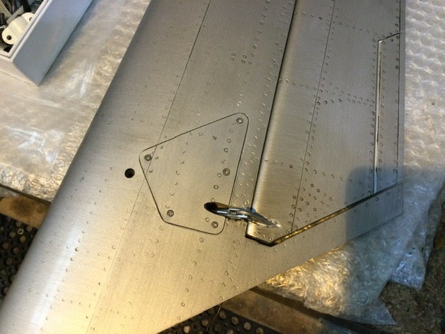
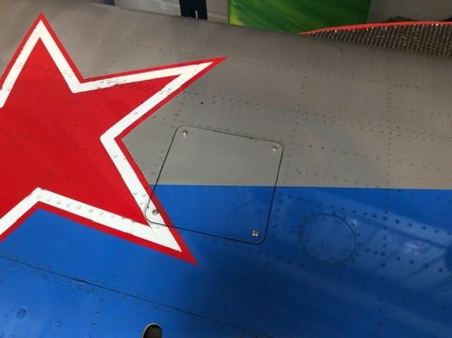
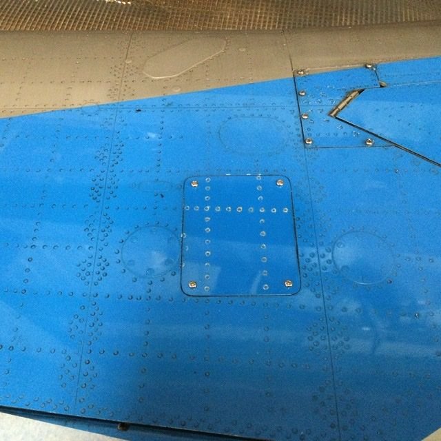
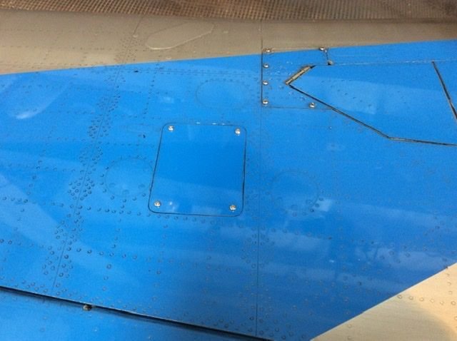
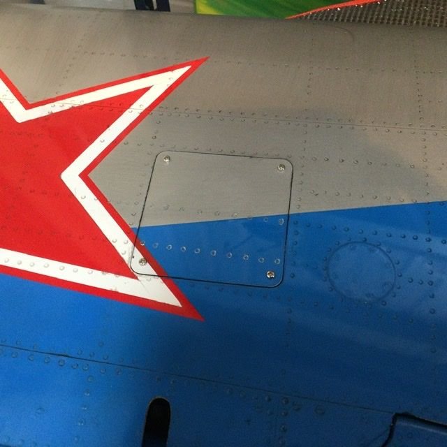
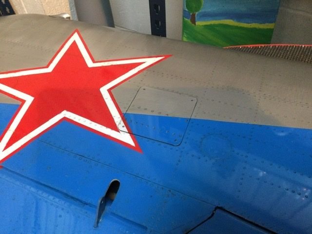
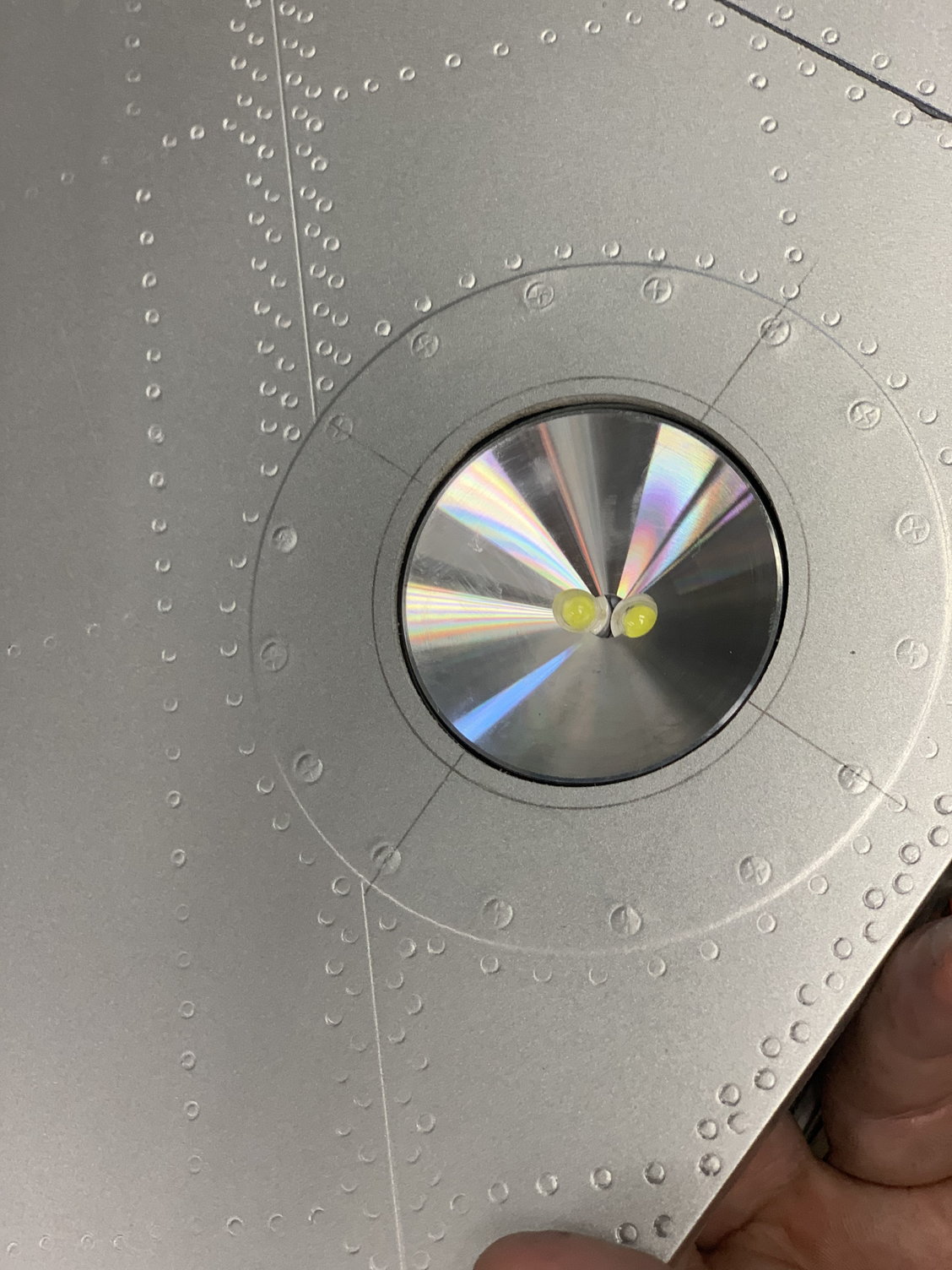
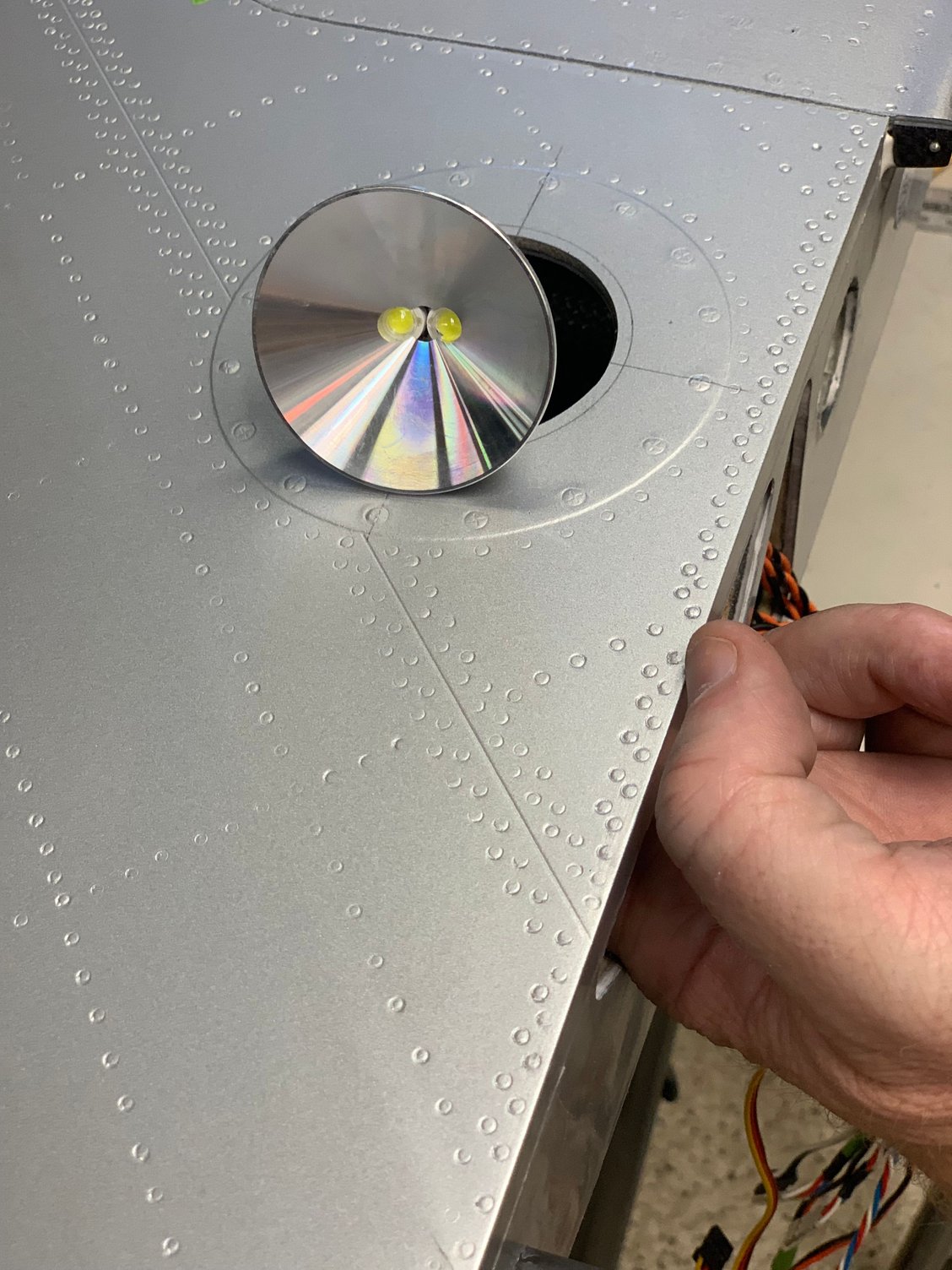
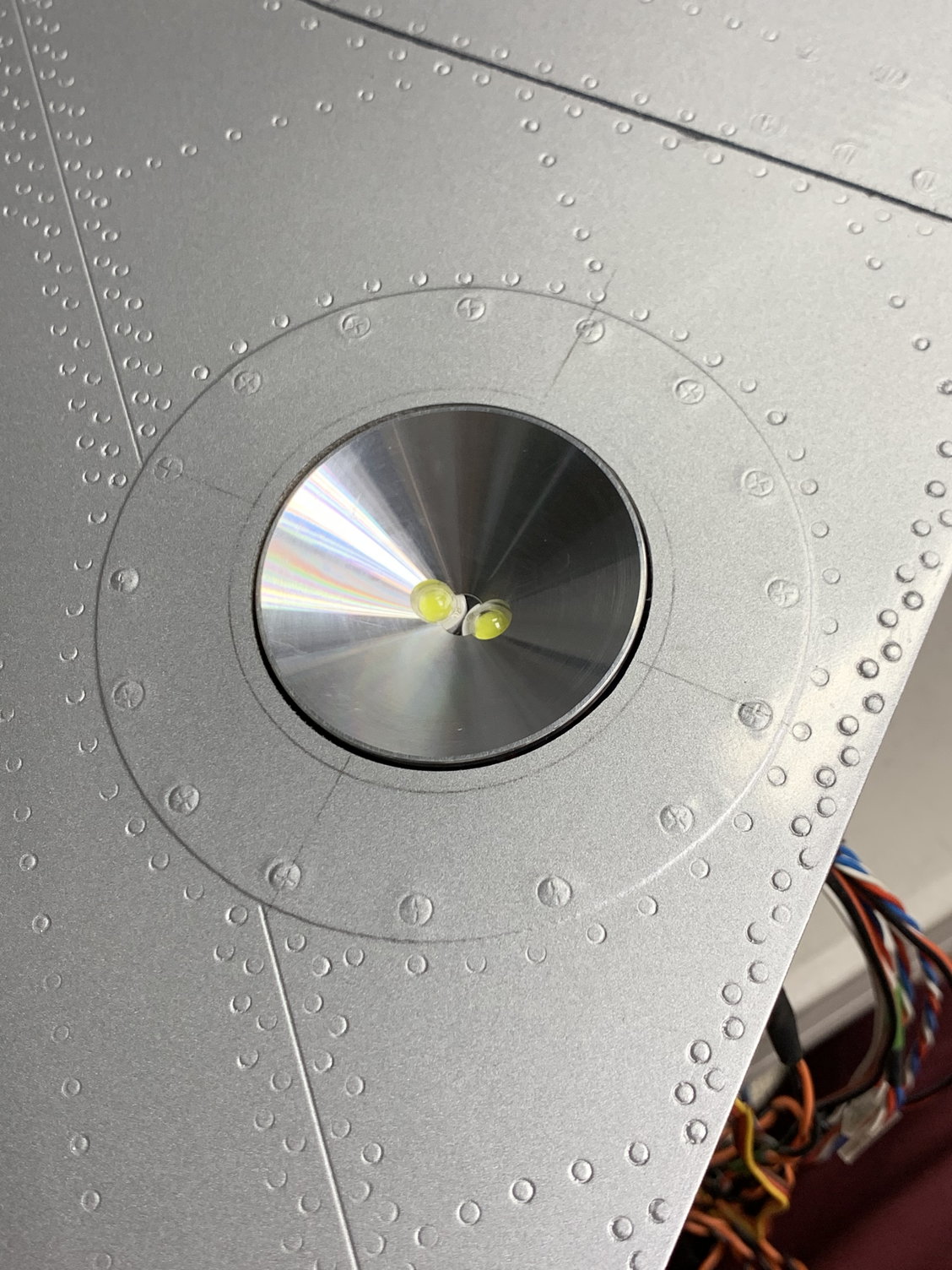
Last post on the build for a while. Added some flight metal around the opening to give it a more scale appearance. Took a new video from a different angle. Slowed the deploy and retract down a bit. I�ll likely move on to the rear fuse section next and install the AB rings and servo leads.
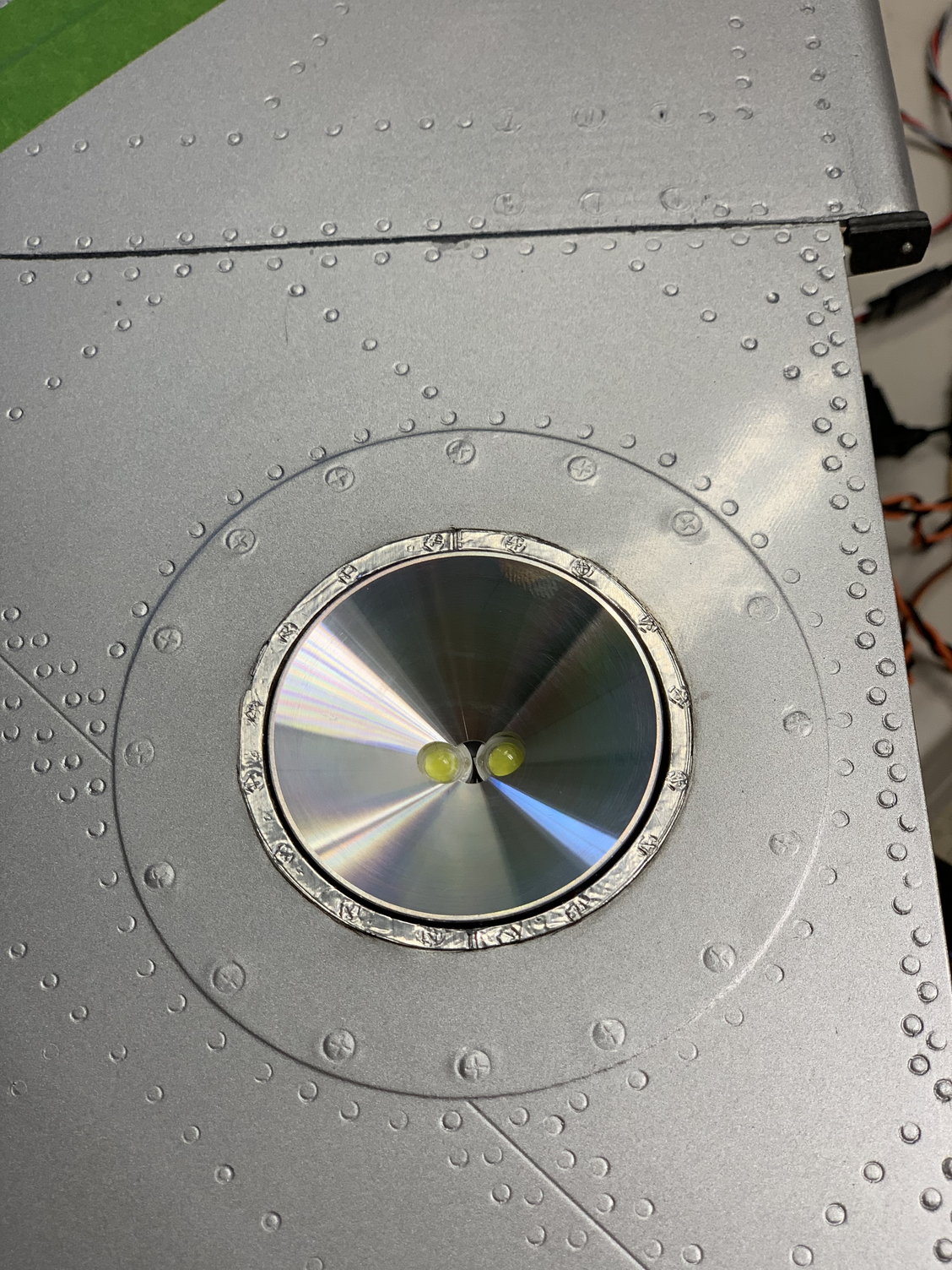
Still photo of the added detail around the opening
Still photo of the added detail around the opening
The following users liked this post:
jackdiazccs (06-16-2022)